
Light Guide Plate and Backlight Module Containing Same

Inactive Publication Date: 2013-10-31
TCL CHINA STAR OPTOELECTRONICS TECH CO LTD
View PDF4 Cites 0 Cited by
  • Summary
  • Abstract
  • Description
  • Claims
  • Application Information

AI Technical Summary

Benefits of technology

The present invention provides a light guide plate with a metal layer that serves to increase the intensity and uniformity of lighting. Additionally, the invention also provides a backlight module that uses the light guide plate with metal layer to prevent light leakage and improve overall lighting performance. The invention is easy to manufacture, low-cost, and can alleviate edge light leakage, improve optical quality, and facilitate bezel slimming of the backlight module.

Problems solved by technology

Thus, the light does not undergo total internal reflection and directly transmits into the optic films, thereby leading to light leakage.
However, since the interface where the side reflection plate 500 is attached to the light guide plate 400 is generally not a smooth surface, scattering reflection of light often occurs at the interface, thereby resulting in light leakage.

Method used


Image

  • Light Guide Plate and Backlight Module Containing Same
  • Light Guide Plate and Backlight Module Containing Same
  • Light Guide Plate and Backlight Module Containing Same

Examples


Embodiment Construction

[0034]To further expound the technical solution adopted in the present invention and the advantages thereof, a detailed description is given to a preferred embodiment of the present invention and the attached drawings.

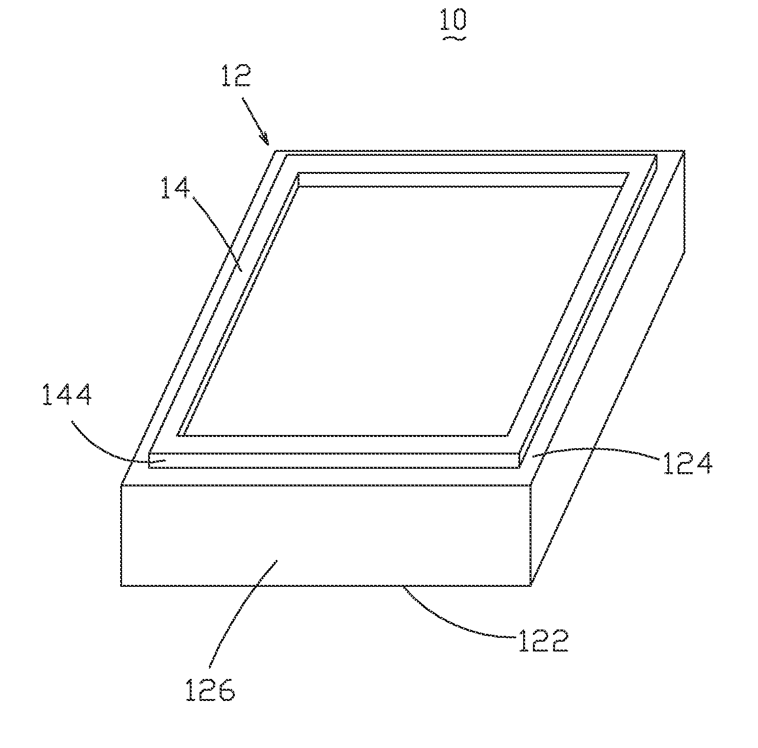
[0035]Referring to FIG. 5, a light guide plate according to an embodiment of the present invention, generally designated at 10, comprises: a plate body 12 and a metal layer 14 formed on the plate body 12. The plate body 12 comprises a bottom face 122, a top face 124 opposite to the bottom face 122, and a plurality of side faces 126 between the bottom face 122 and the top face 124. The metal layer 14 is formed on at least one side edge of the top face 124. The metal layer 14 functions for reflecting light and is thus made of a metal of relatively high reflectivity, such as silver (Ag) and aluminum (Al). The metal is selected according to the wavelength of light emitting from a light source that is used in combination with the light guide plate. In a backlight module, th...


PUM


Abstract

The present invention provides a light guide plate and a backlight module containing the light guide plate. The light guide plate includes a plate body and a metal layer formed on the plate body. The plate body includes a bottom face, a top face opposite to the bottom face, and a plurality of side faces between the bottom face and the top face. The metal layer is formed on at least one side edge of the top face. The metal layer shows reflectivity of which difference is less than 20% for lights having wavelength between 380-780 nm. The light guide plate uses the metal layer formed on the top face to reflect light back into the light guide plate to confine the light within the light guide plate so as to prevent light leakage and ensure light intensity and homogeneity of the light guide plate.

Description

BACKGROUND OF THE INVENTION[0001]1. Field of the Invention[0002]The present invention relates to the field of liquid crystal displaying, and in particular to a light guide plate with metal layer and a backlight module containing the light guide plate.[0003]2. The Related Arts[0004]Liquid crystal display (LCD) has a variety of advantages, such as compact device size, low power consumption, and being free of radiation, and is thus widely used. Most of the LCDs that are currently available in the market are backlighting LCDs, which comprise a liquid crystal panel and a backlight module. The working principle of the liquid crystal panel is that liquid crystal molecules are interposed between two parallel glass substrates and a plurality of vertical and horizontal fine electrical wires is arranged between the two glass substrates, whereby the liquid crystal molecules are controlled to change direction by application of electricity in order to refract light emitting from the backlight mod...

Claims


Application Information

Patent Timeline
IPC IPC(8): F21V8/00F21V7/00
CPCG02B6/0055G02B6/0091
Inventor HU, CHECHANGHE, HU
Owner TCL CHINA STAR OPTOELECTRONICS TECH CO LTD
Features
  • Generate Ideas
  • Intellectual Property
  • Life Sciences
  • Materials
  • Tech Scout
  • Unparalleled Data Quality
  • Higher Quality Content
  • 60% Fewer Hallucinations
Learn More