Fluid supply device

a technology of fluid supply device and fluid supply device, which is applied in the direction of positive displacement liquid engine, electric control, machine/engine, etc., can solve the problems of large size, large size of fluid supply device, and supply device with electric motor driven pump, etc., to achieve the effect of reducing the size and cost of the fluid supply device, reducing the size and cost, and high reliability

Inactive Publication Date: 2013-10-31
IHI AEROSPACE CO LTD
View PDF6 Cites 6 Cited by
  • Summary
  • Abstract
  • Description
  • Claims
  • Application Information

AI Technical Summary

Benefits of technology

[0019]The above-described fluid supply device according to the present invention is designed to control the flow rate of fluid by regulating the rotational speeds of the electric motors, and thus, does not require a regulation valve, a bypass valve or the like. Devices, such as a device for detecting failure of the electric motors and the constant displacement pumps or a device for changing the route of fluid flow, are not required, either. The flow rates in the first and second supply passages are maintained at their respective desired values only by simple feedback control, which allows a reduction in size and cost of the fluid supply device.
[0020]The above-described fluid supply device has a feature that the third and first constant displacement pumps complement each other to maintain the desired flow rate in the first supply passage, while the third and second constant displacement pumps complement each other to maintain the desired flow rate in the second supply passage. This feature enables a great reduction in size and cost of the fluid supply device while keeping high reliability.

Problems solved by technology

The fuel supply device of this type, however, has a disadvantage that it is large in size because of a regulation valve, a bypass valve and the like required to control the flow rate of fuel supplied to the engine.
The fuel supply device with a pump driven by an electric motor has, however, a problem in terms of reliability, since failure of the electric motor, malfunction in the electrical system or the like may lead to interruption of fuel supply to the engine.
However, even with the fuel supply device with a pump driven by a redundant-configuration multiphase motor, failure of the pump may lead to interruption of fuel supply to the engine.

Method used


Image

  • Fluid supply device
  • Fluid supply device
  • Fluid supply device

Examples


first embodiment

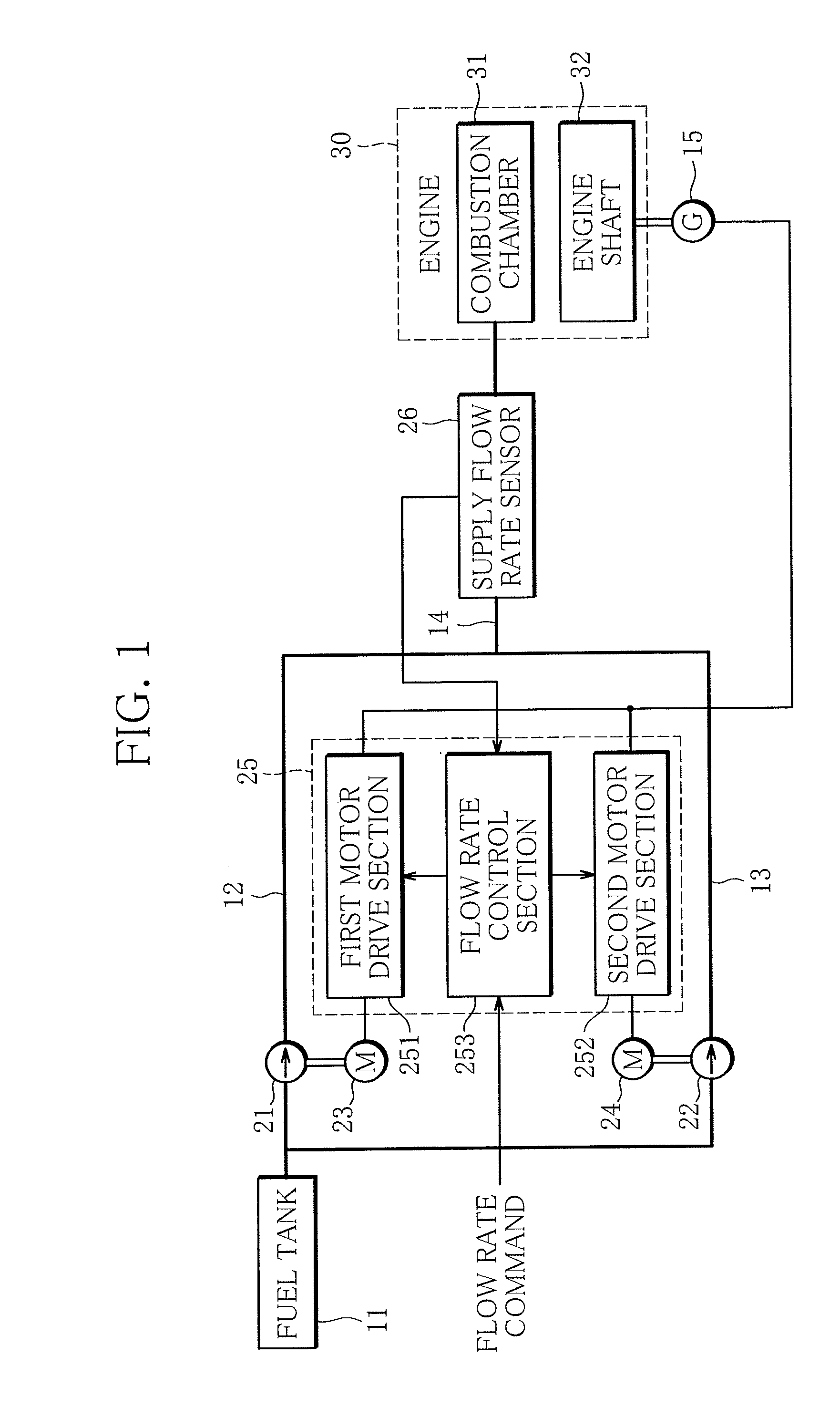
[0027]With reference to FIG. 1, a first embodiment of a fluid supply device, specifically, fuel supply device according to the present invention will be described.

[0028]FIG. 1 is a block diagram showing the configuration of the first embodiment of the fuel supply device.

[0029]The first embodiment of the fuel supply device comprises a fuel tank 11, a first fuel passage 12, a second fuel passage 13, a supply passage 14, an electric generator 15, a first fuel pump 21, a second fuel pump 22, a first electric motor 23, a second electric motor 24, a control device 25 and a supply flow rate sensor 26.

[0030]The fuel tank 11, which is a “reservoir”, holds fuel, which is “fluid”. To the fuel tank 11, the first and second fuel passages 12, 13 are connected. The first and second fuel passages 12, 13 are connected to the supply passage 14 at the other end. The supply passage 14 is connected to a combustion chamber 31 of an engine 30. The engine 30 is an internal combustion engine operating by bu...

second embodiment

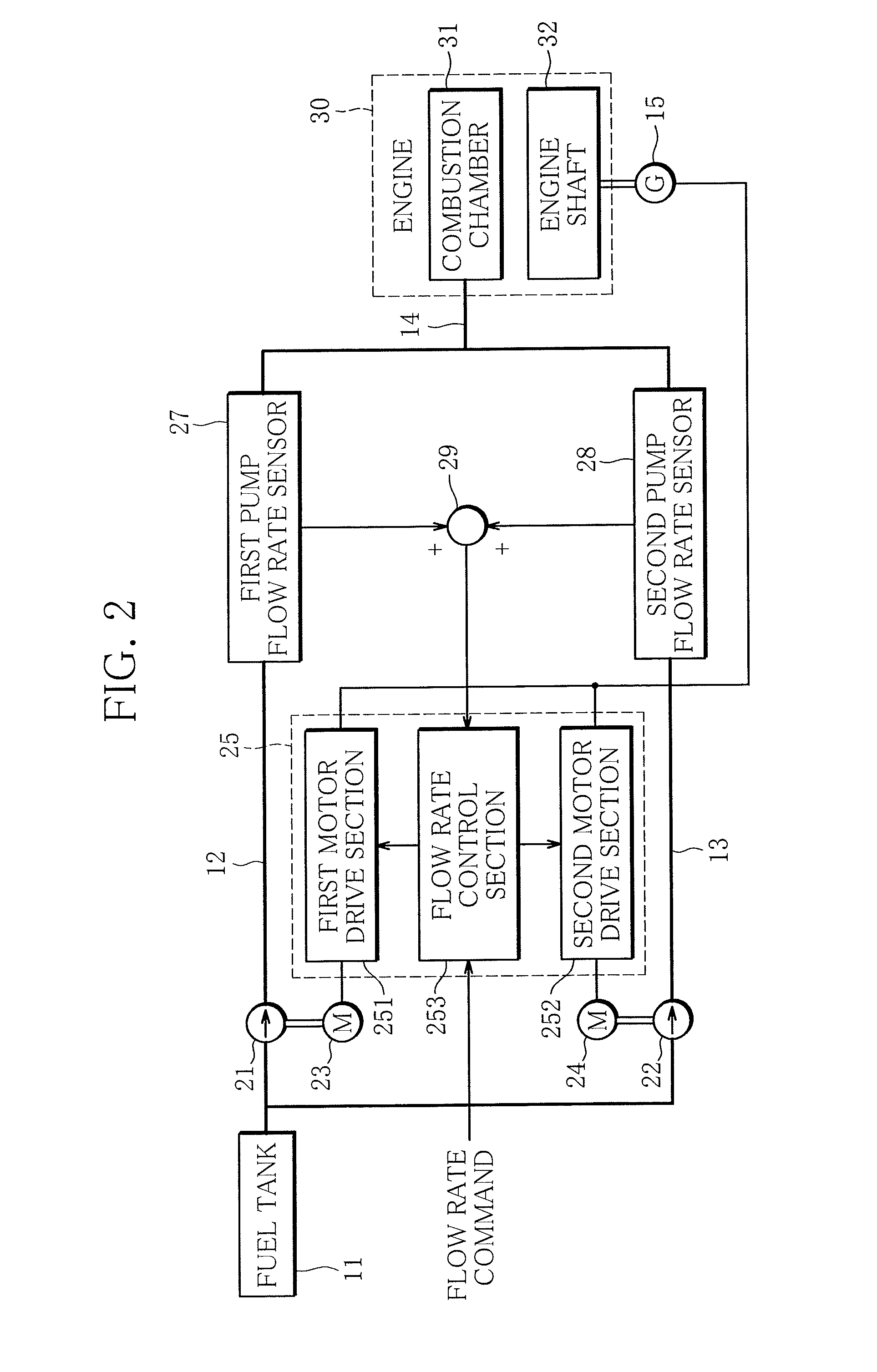
[0041]With reference to FIG. 2, a second embodiment of the fluid supply device, specifically, fuel supply device according to the present invention will be described.

[0042]FIG. 2 is a block diagram showing the configuration of the second embodiment of the fuel supply device.

[0043]The second embodiment of the fuel supply device differs from the first embodiment in that it comprises a first pump flow rate sensor 27, a second pump flow rate sensor 28 and an adder 29 in place of the supply flow sensor 26 of the first embodiment; both embodiments are similar in the other respects. In the following description of the second embodiment, the differences from the first embodiment will be described in detail while the same components as those of the first embodiment, indicated by the same reference characters, will not.

[0044]In the second embodiment, the “flow rate detection device” comprises a first pump flow rate sensor 27, a second pump flow rate sensor 28 and an adder 29. The first pump f...

third embodiment

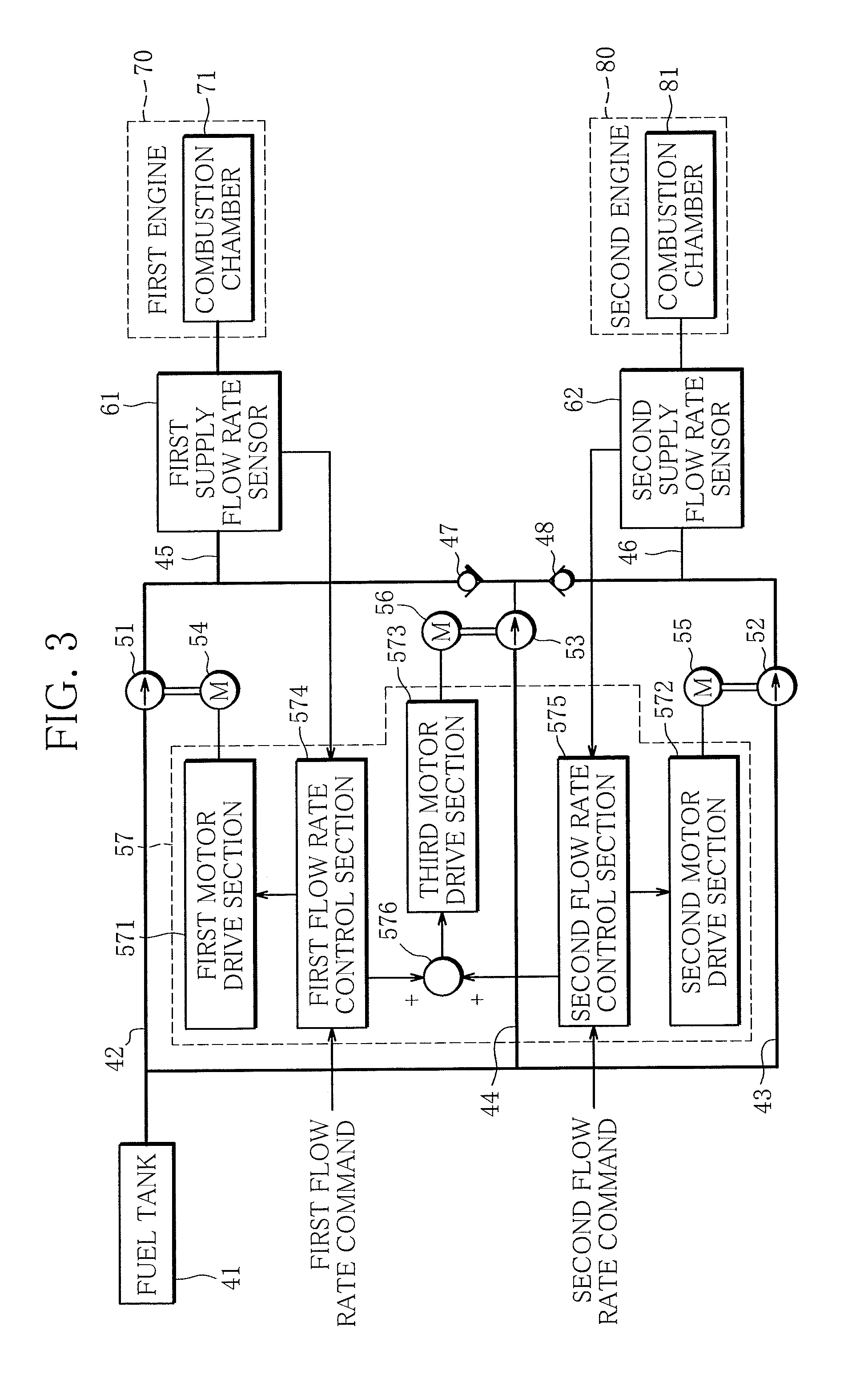
[0046]With reference to FIG. 3, a third embodiment of the fluid supply device, specifically, fuel supply device according to the present invention will be described.

[0047]FIG. 3 is a block diagram showing the configuration of the third embodiment of the fuel supply device.

[0048]The third embodiment of the fuel supply device comprises a fuel tank 41, a first fuel passage 42, a second fuel passage 43, a third fuel passage 44, a first supply passage 45, a second supply passage 46, a first check valve 47 and a second check valve 48.

[0049]The fuel tank 41, which is a “reservoir”, holds fuel, which is “fluid”. To the fuel tank 41, the first, second and third fuel passage 42, 43, 44 are connected. The first fuel passage 42 is connected to the first supply passage 45, the second fuel passage 43 to the second supply passage 46, and the third fuel passage 44 to both the first and second supply passages 45, 46. The first check valve 47 is fitted to a passage between the third fuel passage 44 a...


PUM


Abstract

A fuel supply device according to the present invention comprises a first fuel pump for forcing fuel from a fuel tank to a fuel passage, a first electric motor for driving the first fuel pump, a second fuel pump for forcing fuel from the fuel tank to the fuel passage, a second electric motor for driving the second fuel pump, a supply flow rate sensor for detecting flow rate in the supply passage, and a control device for controlling the flow rate in the supply passage to follow a desired value thereof, by regulating rotational speeds of the first and second electric motors depending on a difference between the desired value and a detected value of flow rate in the supply passage.

Description

BACKGROUND OF THE INVENTION[0001]1. Field of the Invention[0002]The present invention relates to a fluid supply device for supplying fluid from a fluid reservoir to a supply passage.[0003]2. Description of the Related Art[0004]As an example of the fluid supply device for supplying fluid from a fluid reservoir to a fluid passage, a fuel supply device for supplying fuel to an engine of an automobile, an aircraft or the like is a known, wherein a pump driven by the engine accessory gearbox forces fuel from a fuel tank into the engine. The flow rate of fuel delivered by the pump therefore depends on the rotational speed of the engine, and thus, the fuel supply device of this type comprises a regulation valve, a bypass valve and the like to control the flow rate of fuel supplied to the engine (see JP 2008-530442 A).[0005]The fuel supply device with a pump driven by the engine accessory gearbox can continue supplying fuel to the engine as long as the engine is rotating, which is advantage...

Claims


Application Information

Patent Timeline
Patent Type & Authority Applications(United States)
IPC IPC(8): F04B49/06
CPCF04B49/06F02D41/3082F02D41/3845F02M37/00F02M37/18F04B49/20F04B2205/09F04B2207/041F04C14/02F04C14/08
Inventor OYORI, HITOSHIMORIOKA, NORIKO
Owner IHI AEROSPACE CO LTD
Why Eureka
Try Eureka