Cyclone separation device and cyclone vacuum cleaner mounted with same

a separation device and vacuum cleaner technology, applied in the direction of cleaning filter means, cleaning equipment, separation processes, etc., can solve the problems of affecting the cleaning effect later, both ends of the dirty substance are subject to substantially the same force, and cannot escape, so as to improve the overall efficiency of the vacuum cleaner, reduce the accumulation of dust, and simple structure

Active Publication Date: 2013-11-07
ECOVACS ROBOTICS (SUZHOU ) CO LTD
View PDF0 Cites 50 Cited by
  • Summary
  • Abstract
  • Description
  • Claims
  • Application Information

AI Technical Summary

Benefits of technology

[0029]The cyclone separation device of the present invention features simple structure, the airflow entering the second cyclone separation unit is evenly distributed into each of the cyclone barrels. Under a predetermined cross-sectional area of cyclone barrels, the cross-sectional areas of two a

Problems solved by technology

Additionally, in such design of airflow passages, because the adjacent airflow passages have substantially the same wind speed, both ends of the dirty substances are subjected to substantially the same force.
When the dirty substances are blocked

Method used


Image

  • Cyclone separation device and cyclone vacuum cleaner mounted with same
  • Cyclone separation device and cyclone vacuum cleaner mounted with same
  • Cyclone separation device and cyclone vacuum cleaner mounted with same

Examples


embodiment 1

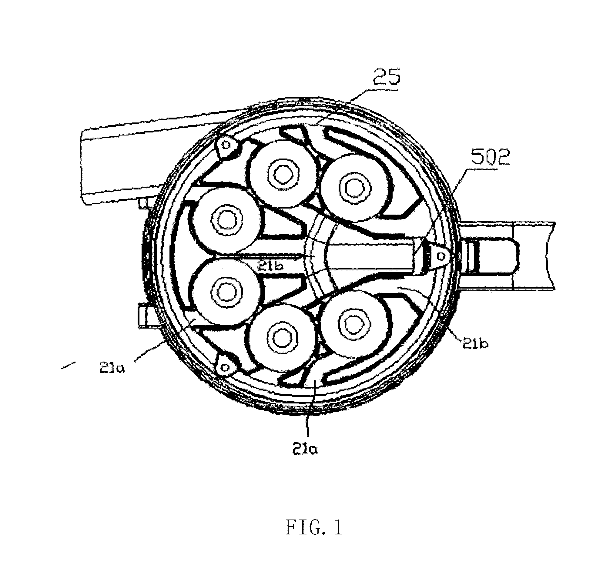
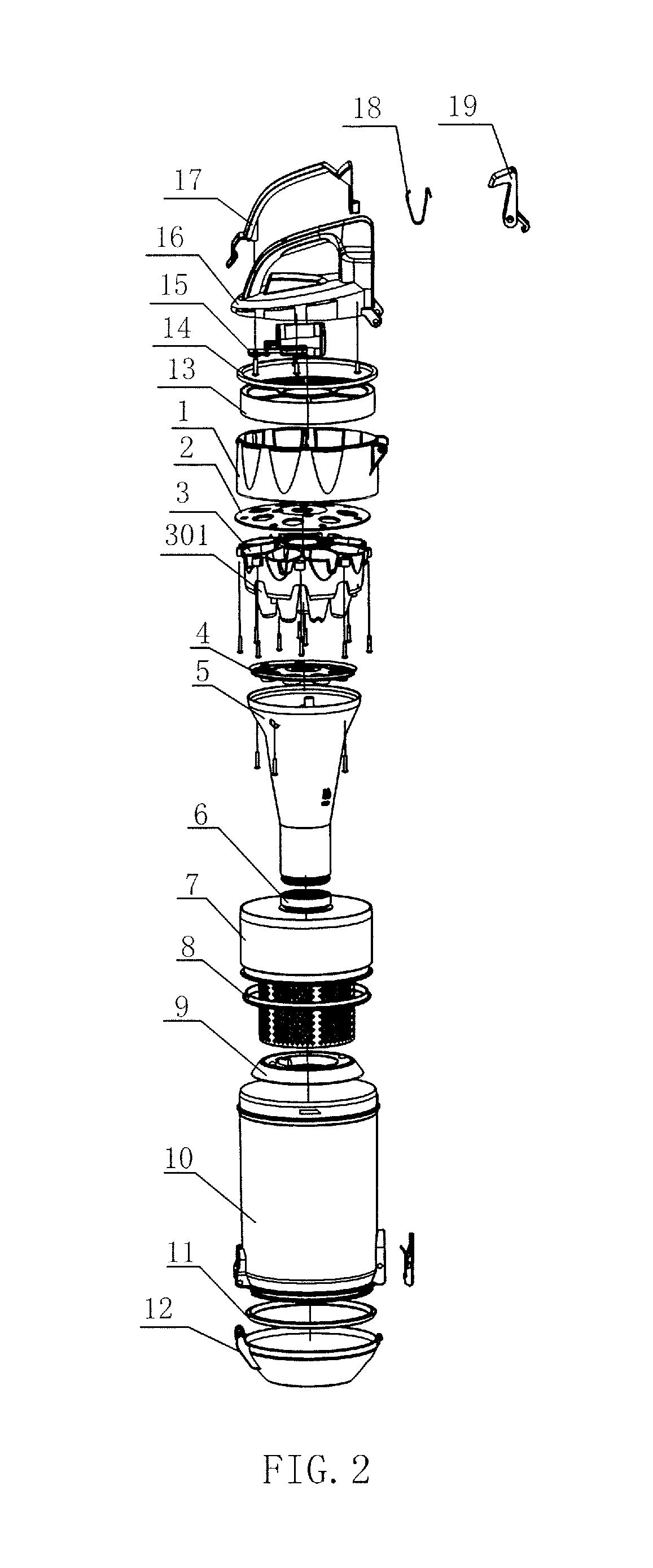
[0038]As shown in FIGS. 2 and 3, the cyclone separation device of the present invention comprises a first cyclone separation unit and a second cyclone separation unit. The first cyclone separation unit comprises a dust bucket 10 and a mesh filter 7. The dust bucket 10 is provided with a tangential air inlet 10a and is used to perform the gas-solid separation among the gas and the dirt such as particles, and its bottom is used to collect dirt; The mesh filter 7 is provide with a plurality of air holes 7a, which are through holes. The second cyclone separation unit is located at the downstream of the first cyclone separation unit, and comprises a separator 3 and a connecting barrel 5. The separator 3 is configured to filter small particles of dirt, and comprises a plurality of cyclone barrels 31, both the upper ends and lower ends of the cyclone barrels 31 are opened; Two tangential air inlets are provided on the side walls of the cyclone barrels 31. Specifically, these two air inlets...

second embodiment

[0045]FIG. 6 schematically shows the structure of the separator in the cyclone separation device according to the second embodiment of the present invention. As shown in FIG. 6, the second embodiment differs from the first embodiment only in that: the separator 3 according to the second embodiment is configured by enclosing a plurality of cyclone barrels 31, and the external surfaces of the plurality of cyclone barrels 31 do not include an outer wall with recess. This separator 3 is placed on a connecting barrel with a gap therebetween, and the connecting barrel has been mounted with a collecting barrel sealing cover.

[0046]In this cyclone separation device, after a gas-solid separation by the first cyclone separation unit, the separated airflow enters into the second cyclone separation unit. The airflow after this first separation is branched into the first airflow and the second airflow. The first airflow travels in the same way as that of the first embodiment, that is, the first c...


PUM

PropertyMeasurementUnit
Angleaaaaaaaaaa
Angleaaaaaaaaaa
Angleaaaaaaaaaa

Abstract

A cyclone separation device (102, 202) and a cyclone vacuum cleaner (100, 200) mounted with the device. A first cyclone separation unit in the cyclone separation device (102, 202) comprises a dust bucket (10) and a mesh filter (7) with air holes (7a). Airflow enters the first cyclone separation unit to undergo first gas-solid separation. The airflow after the separation enters a second cyclone separation unit through the air holes (7a) of the mesh filter (7). A filter in the second cyclone separation unit comprises a plurality of cyclone barrels (31). An upper end and a lower end of the cyclone barrel (31) are open. A first air inlet (31a) and a second air inlet (31b) are disposed on a side wall of the cyclone barrel (31). The airflow (41a, 41b) after the gas-solid separation enters the first air inlet (31a) and the second air inlet (31b) through a first airflow passage and a second airflow passage respectively, is mixed in the cyclone barrel (31), and then undergoes second gas-solid separation. The airflow after the gas-solid separation is discharged from an opening at the upper end of the cyclone barrel (31). In the cyclone separation device (102, 202), the direction of travel of the airflow and the cross-sectional area of the air inlet are changed, thereby improving a separation effect. The cyclone vacuum cleaner (100, 200) mounted with the cyclone separation device (102, 202) increases separation efficiency and improves an air purification effect.

Description

FIELD OF THE INVENTION[0001]The present invention belongs to the technical field of cleaning equipment, and relates to a cyclone separation device and a cyclone vacuum cleaner mounted with such device.DESCRIPTION OF THE PRIOR ART[0002]A vacuum cleaner is configured to clean dust with a negative pressure generated by its built-in motor-driven air blower. During its operation, the vacuum cleaner can suck out the dust in the slits or on the carpet which are uneasy to be removed in normal way while not making the dust floating upward, which has the advantages of convenient usage and easy operation, so such vacuum cleaner is widely used either at home or in public.[0003]As the living conditions of the people are increasingly improved, their consciousness to environmental protection is also gradually heightened, that is, the users not only require that the vacuum cleaner can effectively collect dust, some other factors such as service life, noise and dust collection efficiency are also th...

Claims


Application Information

Patent Timeline
IPC IPC(8): A47L9/16
CPCA47L9/1625A47L9/1641A47L9/165
Inventor PENG, ZHONGMEI
Owner ECOVACS ROBOTICS (SUZHOU ) CO LTD
Why Eureka
Try Eureka