

Speaker Leak Test System and Method
- Summary
- Abstract
- Description
- Claims
- Application Information
AI Technical Summary
Benefits of technology
Problems solved by technology
Method used
Image

Examples
Embodiment Construction
[0020]The following description is of the best mode presently contemplated for carrying out the invention. This description is not to be taken in a limiting sense, but is made merely for the purpose of describing one or more preferred embodiments of the invention. The scope of the invention should be determined with reference to the claims.
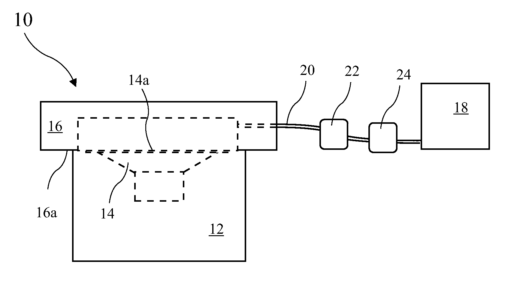
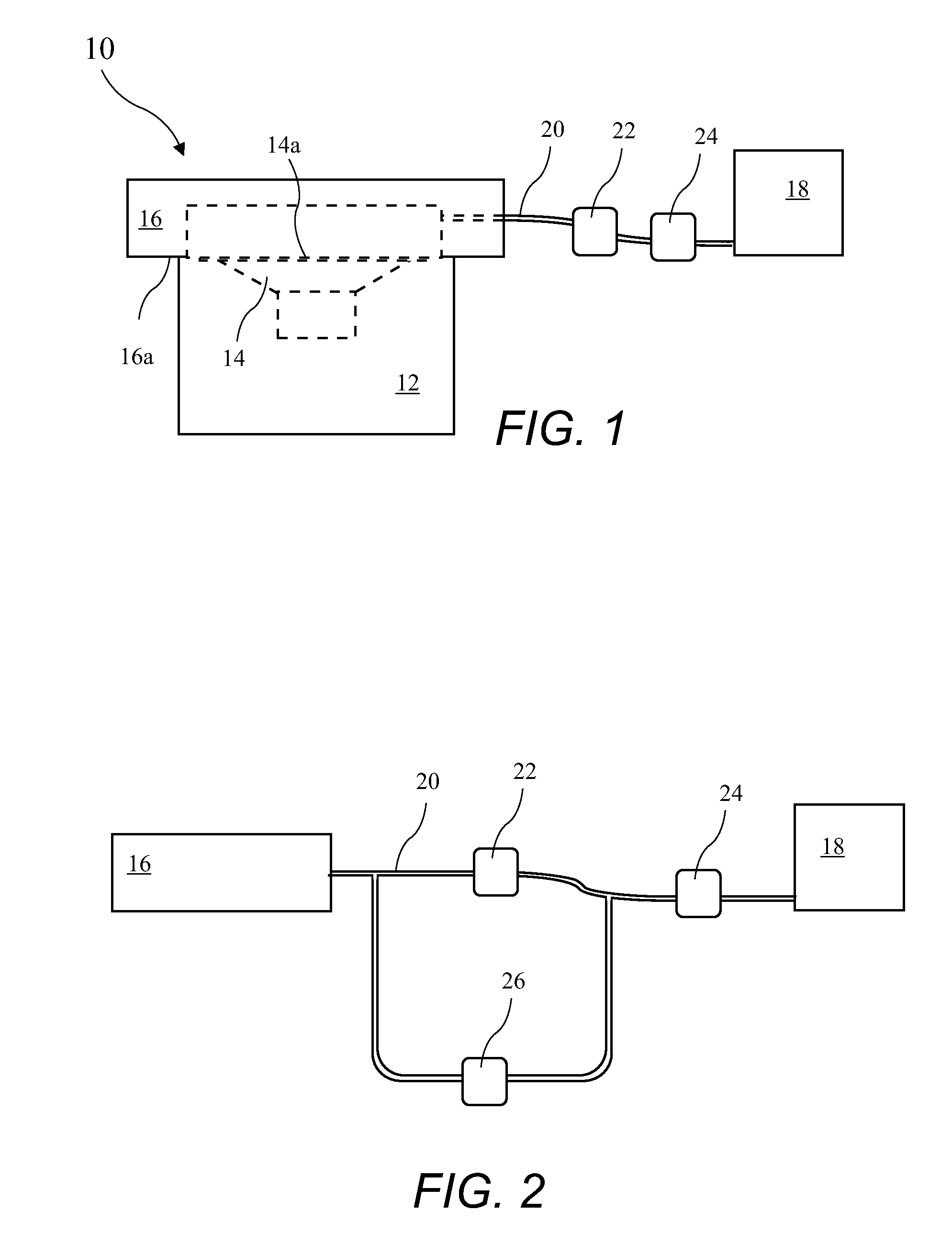
[0021]A speaker enclosure 12 leak test system 10 is shown in FIG. 1. The leak test system 10 includes a mating plate (e.g., a vacuum plate) 16, an air flow source (e.g., a vacuum source) 18, an air hose (e.g. a vacuum hose) 20, a mass air flow sensor 22 and an air flow regulator (e.g., a vacuum regulator) 24. The speaker enclosure 12 is in contact with a vacuum surface 16a of the vacuum plate 16, with a speaker opening 14a of the enclosure 12 against the vacuum surface 16a. Vacuum is applied by the vacuum source 18 through the hose 20, and the mass air flow is measured by the mass air flow sensor 22. The vacuum regulator 24 controls the air flow d...
PUM
 Abstract
Description
Claims
Application Information