
Method for testing flash memory power loss recovery

Active Publication Date: 2005-05-19
MICRON TECH INC
View PDF25 Cites 68 Cited by
  • Summary
  • Abstract
  • Description
  • Claims
  • Application Information

AI Technical Summary

Benefits of technology

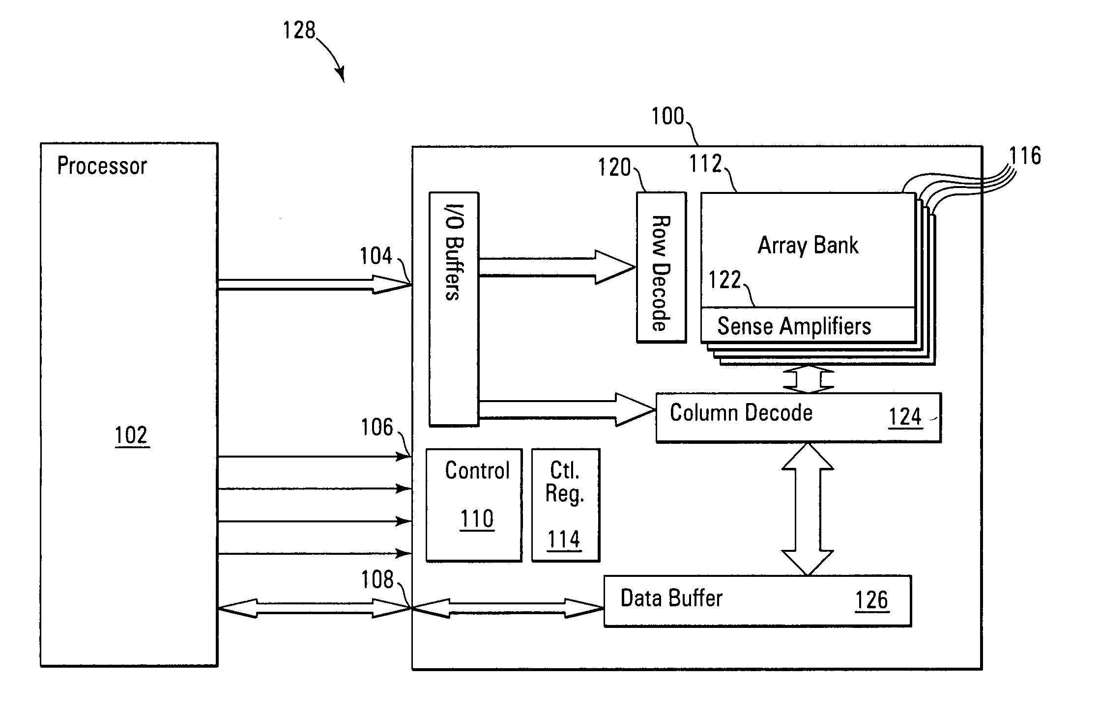
[0011] The various embodiments of the present invention relate to deterministic testing and verification of non-volatile memories, non-volatile memory drivers, write operations / cycles, block erase operations / cycles, non-volatile memory management operations, and power loss recovery testing. The memory device and software embodiments of the present invention utilize write or erase cycle tracking to interrupt or stop a non-volatile memory programming operation at a selected point. This ability to utilize write or erase cycle tracking to interrupt or stop a non-volatile memory programming operation at a selected point allows for halting or interrupting execution at each point in a selected operation that a non-volatile memory cell is programmed or erased. This allows for a deterministic and repeatable testing process of all stages of a write cycle or erase cycle where the state of non-volatile memory cells are changed in the non-volatile memory device. This also allows for step-through testing of each stage by programmer / designer of state changes non-volatile memory cells in the non-volatile memory device or driver software, enabling quick testing and easy logic and code changes, saving time and resources. Additionally, this ability to utilize write or erase cycle tracking to interrupt or stop a non-volatile memory programming operation at a selected point enables simulation of power loss at each point in a selected operation that a non-volatile memory cell is programmed or erased, allowing for improved, deterministic testing of the power loss recovery cycle and faster code / design change verification.

Problems solved by technology

Most RAM is volatile, which means that it requires a steady flow of electricity to maintain its contents.
As soon as the power is turned off, whatever data was in RAM is lost.
Self contained and separately loadable drivers also exist, but are typically not utilized in embedded processor devices.
A problem with utilizing Flash memory devices, particularly in embedded processor or portable battery powered systems, is dealing with potentially intermittent power sources or power availability.
However, as data write operations, block erasures, and other internal Flash management operations that store or change data or the operating state of the Flash memory device are generally not single step operations, the Flash memory can be left in an incomplete state by a power loss event.
This approach is problematic in that it is empirically based and cannot completely guarantee even after a large number of testing cycles that an error is not present in the power loss recovery cycle or routines; the true coverage of the test is unknown.
This form of testing is also time consuming and requires exhaustive testing or retesting when a section of code or hardware is written or changed to verify its correct operation.

Method used


Image

  • Method for testing flash memory power loss recovery
  • Method for testing flash memory power loss recovery
  • Method for testing flash memory power loss recovery

Examples


Embodiment Construction

[0020] In the following detailed description of the invention, reference is made to the accompanying drawings that form a part hereof, and in which is shown, by way of illustration, specific embodiments in which the invention may be practiced. In the drawings, like numerals describe substantially similar components throughout the several views. These embodiments are described in sufficient detail to enable those skilled in the art to practice the invention. Other embodiments may be utilized and structural, logical, and electrical changes may be made without departing from the scope of the present invention. The following detailed description is, therefore, not to be taken in a limiting sense, and the scope of the present invention is defined only by the appended claims and equivalents thereof.

[0021] Embodiments of the present invention include non-volatile memory drivers, testing methods, and apparatuses that allow for deterministic testing and verification of non-volatile memories...


PUM


Abstract

Non-volatile memory device, driver, and method is described that utilizes write or erase cycle tracking to interrupt or stop a non-volatile memory programming or erase operation at a selected point to interrupt / stop execution or simulate power loss at a specific point. This ability allows for a deterministic and repeatable testing process of all write or erase cycles of a non-volatile command where the state of floating gate memory cells are changed in the non-volatile memory device. Additionally, this ability to utilize write or erase cycle tracking to interrupt or stop a non-volatile memory programming operation or erasing operation at any selected point enables simulation of power loss at each point in a selected operation that a non-volatile floating gate memory cell is programmed or erased, allowing for improved, deterministic testing of the power loss recovery cycle and faster code / design change verification.

Description

TECHNICAL FIELD OF THE INVENTION [0001] The present invention relates generally to non-volatile memory devices and in particular the present invention relates to Flash memory device management software, drivers, and power loss recovery testing. BACKGROUND OF THE INVENTION [0002] Memory devices are typically provided as internal storage areas in a computer. The term memory identifies data storage that comes in the form of integrated circuit chips. There are several different types of memory used in modern electronics, one common type is RAM (random-access memory). RAM is characteristically found in use as main memory in a computer environment. RAM refers to read and write memory; that is, you can both write data into RAM and read data from RAM. This is in contrast to ROM (read-only memory), which permits you only to read data. Most RAM is volatile, which means that it requires a steady flow of electricity to maintain its contents. As soon as the power is turned off, whatever data was...

Claims


Application Information

Patent Timeline
IPC IPC(8): G06F13/28G11C29/50
CPCG11C16/04G11C2029/5002G11C29/50004G11C29/50
Inventor WONG, WANMOMUTHUSAMY, KARUNAKARAN
Owner MICRON TECH INC
Learn More