

Screen printing plate for solar cell and method for printing solar cell electrode
a technology of solar cells and printing plates, applied in the field of screen printing plates, can solve the problems of reducing the fill factor, affecting the aesthetic appearance of solar cells, and difficult to gain a height, so as to prevent the connection, and reduce the cost of manufacturing solar cells
Active Publication Date: 2013-11-07
SHIN ETSU CHEM IND CO LTD
View PDF7 Cites 20 Cited by
- Summary
- Abstract
- Description
- Claims
- Application Information
AI Technical Summary
Benefits of technology
The invention describes a screen printing plate that can be used to print solar cell electrodes. By using this plate, solar cells can be manufactured more efficiently, at a lower cost. Additionally, the plate helps prevent the connection between bus bar electrodes and finger electrodes from breaking without increasing shadow loss or compromising the aesthetic appearance of solar cells. Finally, the plate helps manufacture reliable solar cells at high productivity.
Problems solved by technology
However, the former method is undesirable because the step of forming grooves in a substrate can cause damage to the substrate.
Since the latter, inkjet printing method is designed to apply pressure to liquid to inject droplets through a thin nozzle, it is suitable to form fine lines, but difficult to gain a height.
However, when fine lines are printed using the above method, there arise a problem that the connection between bus bar electrode and finger electrode becomes very thin and at the worst, broken.
If the finger electrode on the light-receiving side is locally thinned or even broken, that portion becomes a controlling factor of resistance, resulting in a drop of fill factor.
The cause of breakage is a difference in film thickness at the connection between bus bar electrode and finger electrode.
Further, in the screen printing process, the printing direction (traversing direction of a printing squeegee) also becomes a factor of promoting breakage.
Even when a finger electrode and a bus bar electrode are separately printed, a saddle phenomenon occurs at the bus bar electrode, failing to prevent breakage at the connection between bus bar electrode and finger electrode.
On use of this method, however, blurs or clumps form because the connection between bus bar electrode and finger electrode is extremely thick.
This gives rise to problems like an increased shadow loss and deteriorated properties.
The method of the above patent has the problem that since the connection between bus bar electrode and finger electrode is thick, the finger electrode becomes discontinuous in width, detracting from the aesthetic appearance.
This method, however, has the problem that since the squeegee travel direction is not parallel to the finger opening, the finger electrode is blurred, failing in precise printing.
Method used
View moreImage
Smart ImageViewing Examples

Examples
examples
[0059]Examples and Comparative Examples are given below by way of illustration and not by way of limitation.
Login to View More PUM
 Abstract
The present invention relates to screen printing plate for a solar cell in which an electroconductive paste is used to simultaneously print a bus bar electrode and a finger electrode, the screen printing plate characterized in that the opening width of a finger electrode opening of the screen printing plate is less than 80 μm and a bus bar electrode opening of the screen printing plate has a closed section. The use of this screen printing plate makes it possible to reduce the cost of manufacturing solar cells, prevent the connecting section between the bus bar electrode and the finger electrode from breaking without causing an increase in shadow loss or compromising the aesthetic quality of the solar cells, and manufacture highly reliable solar cells with good productivity.
Description
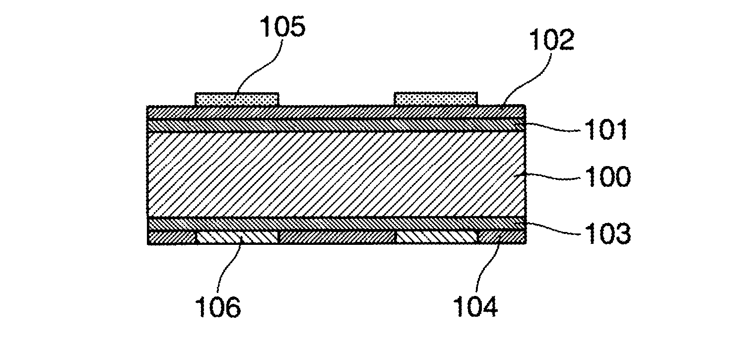
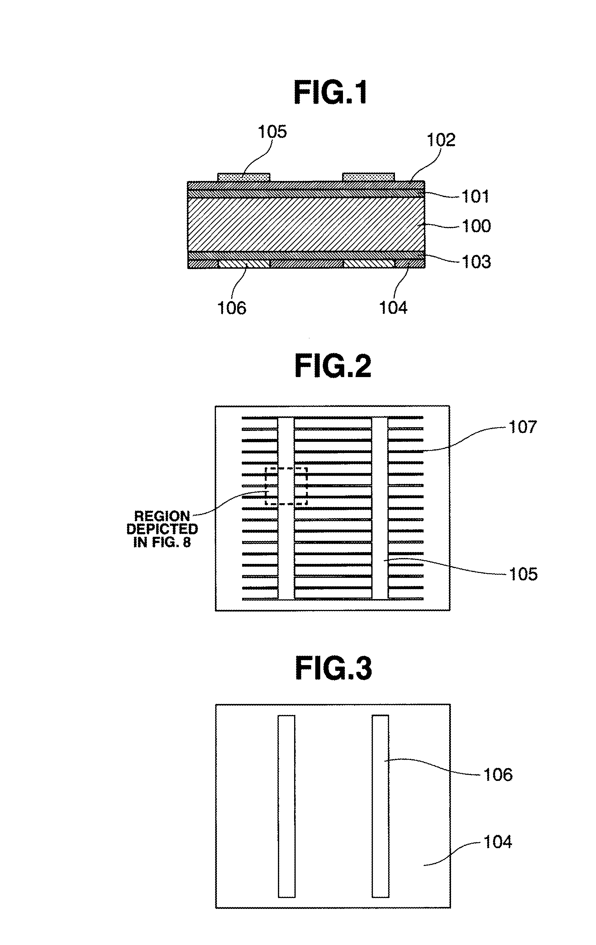
TECHNICAL FIELD[0001]This invention relates to a screen printing plate which enables manufacture of solar cells with long-term reliability at good productivity. More particularly, it relates to a screen printing plate whose bus bar electrode mask pattern is modified such that electrodes may be formed at low cost while maintaining high conversion efficiency; and a method of printing solar cell electrodes using the screen printing plate.BACKGROUND ART[0002]A solar cell manufactured by the prior art technology is described with reference to its cross-sectional view (FIG. 1), front surface configuration (FIG. 2), and back surface configuration (FIG. 3). In general, the solar cell includes a p-type semiconductor substrate 100 of silicon or the like in which an n-type dopant is diffused to form an n-type diffusion layer 101 to define a p-n junction. On the n-type diffusion layer 101, an antireflection film 102 such as SiNx film is formed. On the back surface of p-type semiconductor substr...
Claims
Login to View More Application Information
Patent Timeline
 IPC IPC(8): B41N1/24
CPCB41N1/248H01L31/022425B41N1/24H01L31/1804Y02E10/547H01L31/068H01L31/022433Y02P70/50H01L31/0201
InventorENDO, YOKOMITTA, RYOWATABE, TAKENORIOTSUKA, HIROYUKI
OwnerSHIN ETSU CHEM IND CO LTD