

Discontinuous loop antennas suitable for radio-frequency identification (RFID) tags, and related components, systems, and methods
a loop antenna and radio frequency identification technology, applied in the field of antennas, can solve the problems of rapid decrease in power of near-field effects and compounded rfid impedance mismatch, and achieve the effects of increasing power harvesting efficiency, increasing near-field sensitivity, and increasing near-field sensitivity
- Summary
- Abstract
- Description
- Claims
- Application Information
AI Technical Summary
Benefits of technology
Problems solved by technology
Method used
Image

Examples
Embodiment Construction
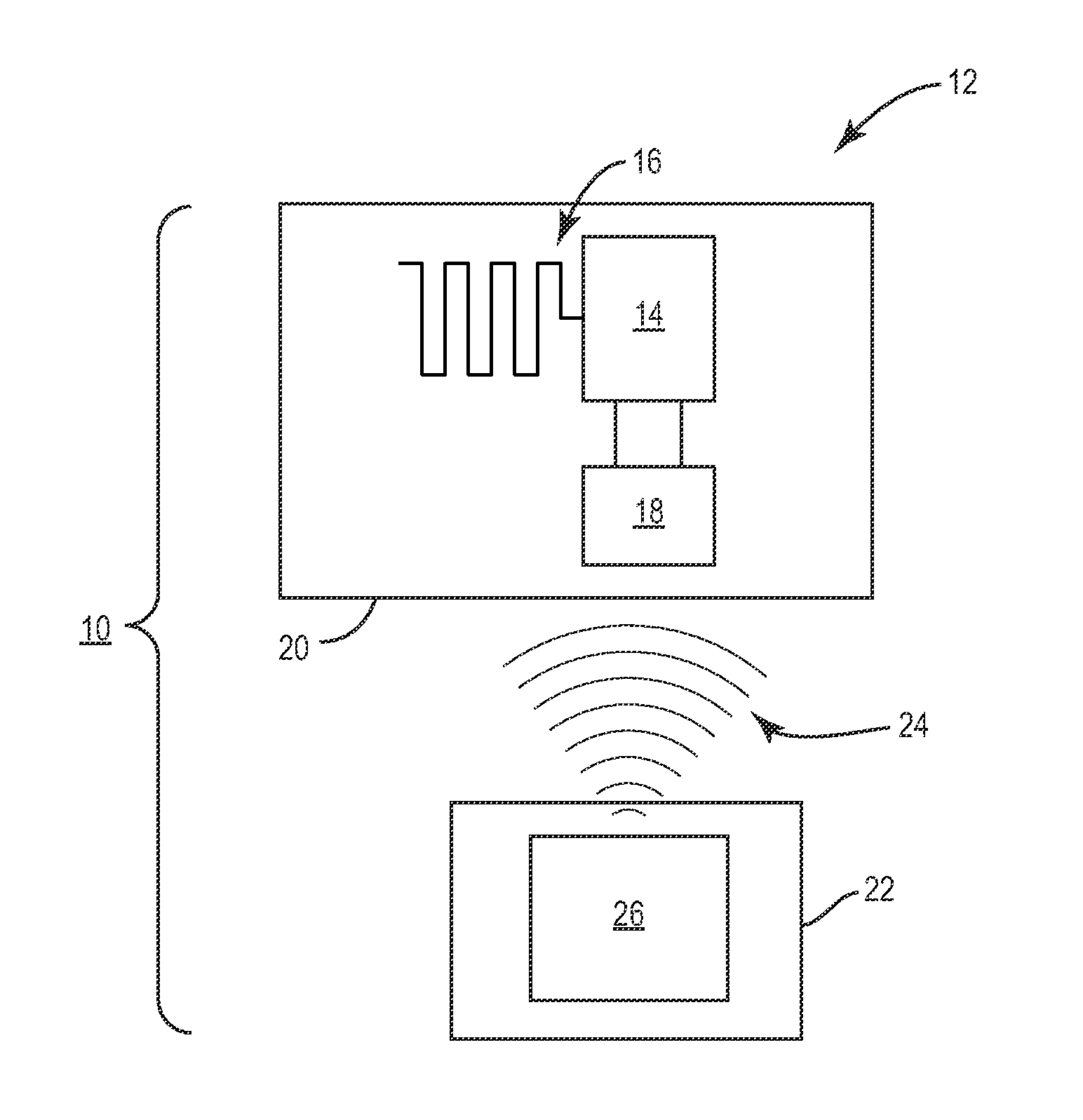
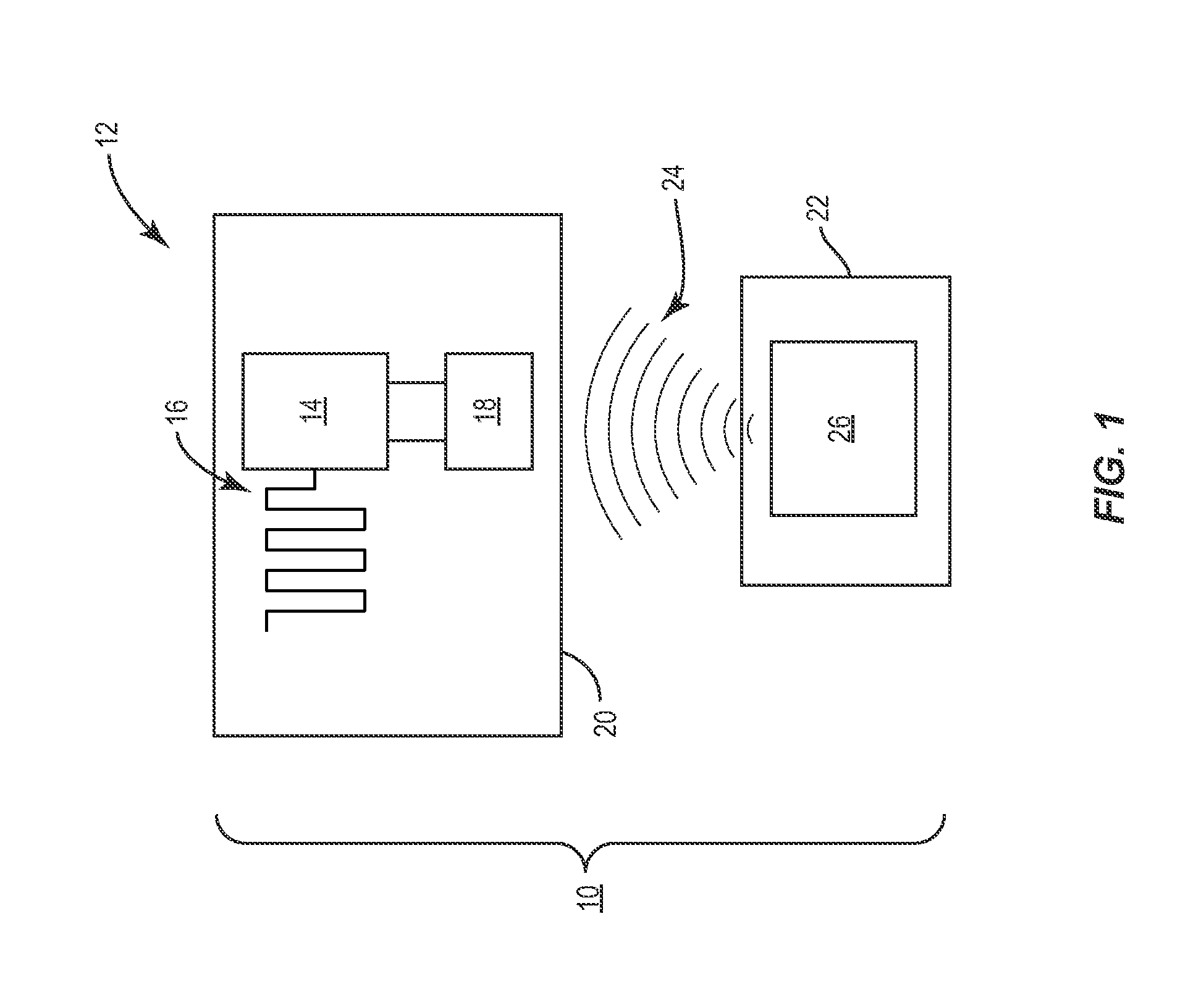
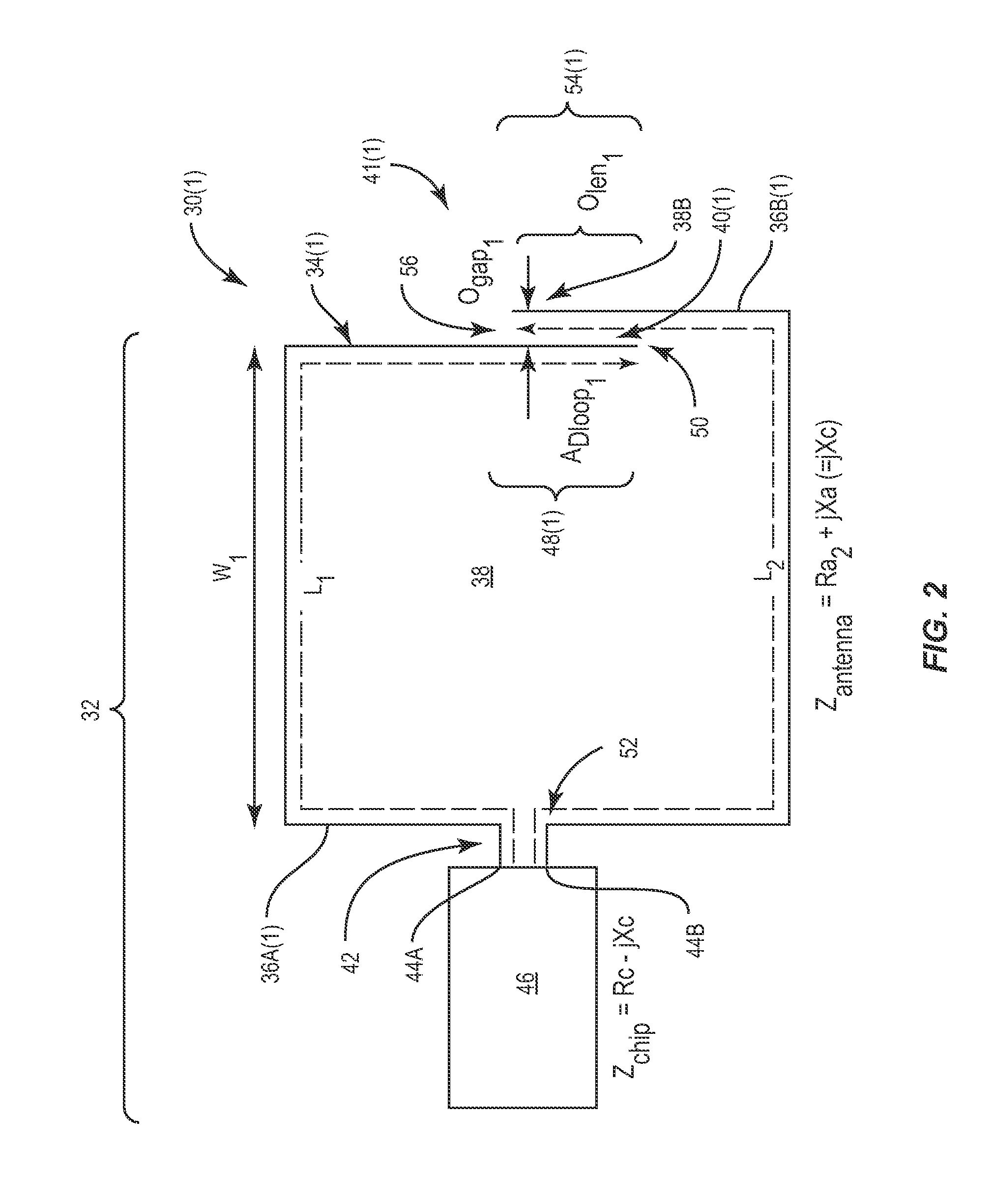
[0008]Embodiments disclosed in the detailed description include discontinuous loop antennas. Related components, tags, systems, and methods are also disclosed. A discontinuous loop antenna is an antenna loop structure that includes a discontinuity portion. The discontinuous loop antenna can be coupled to an RFID chip to provide an RFID tag as a non-limiting example. The discontinuity portion allows the discontinuous loop antenna to have magnetic field sensitivity at greater than one wavelength of the discontinuous loop antenna. Thus, the discontinuous loop antenna has significantly increased near-field sensitivity over other antennas. Increased near-field sensitivity provides increased power harvesting efficiency during near-field coupling. As one non-limiting example, an RFID tag having a discontinuous loop antenna may achieve up to one hundred (100) times more power harvesting from a radio-frequency (RF) signal than an RFID tag having a continuous loop antenna tuned to the same or...
PUM
| Property | Measurement | Unit |
|---|---|---|
| center frequencies | aaaaa | aaaaa |
| center frequencies | aaaaa | aaaaa |
| center frequencies | aaaaa | aaaaa |
Abstract
Description
Claims
Application Information