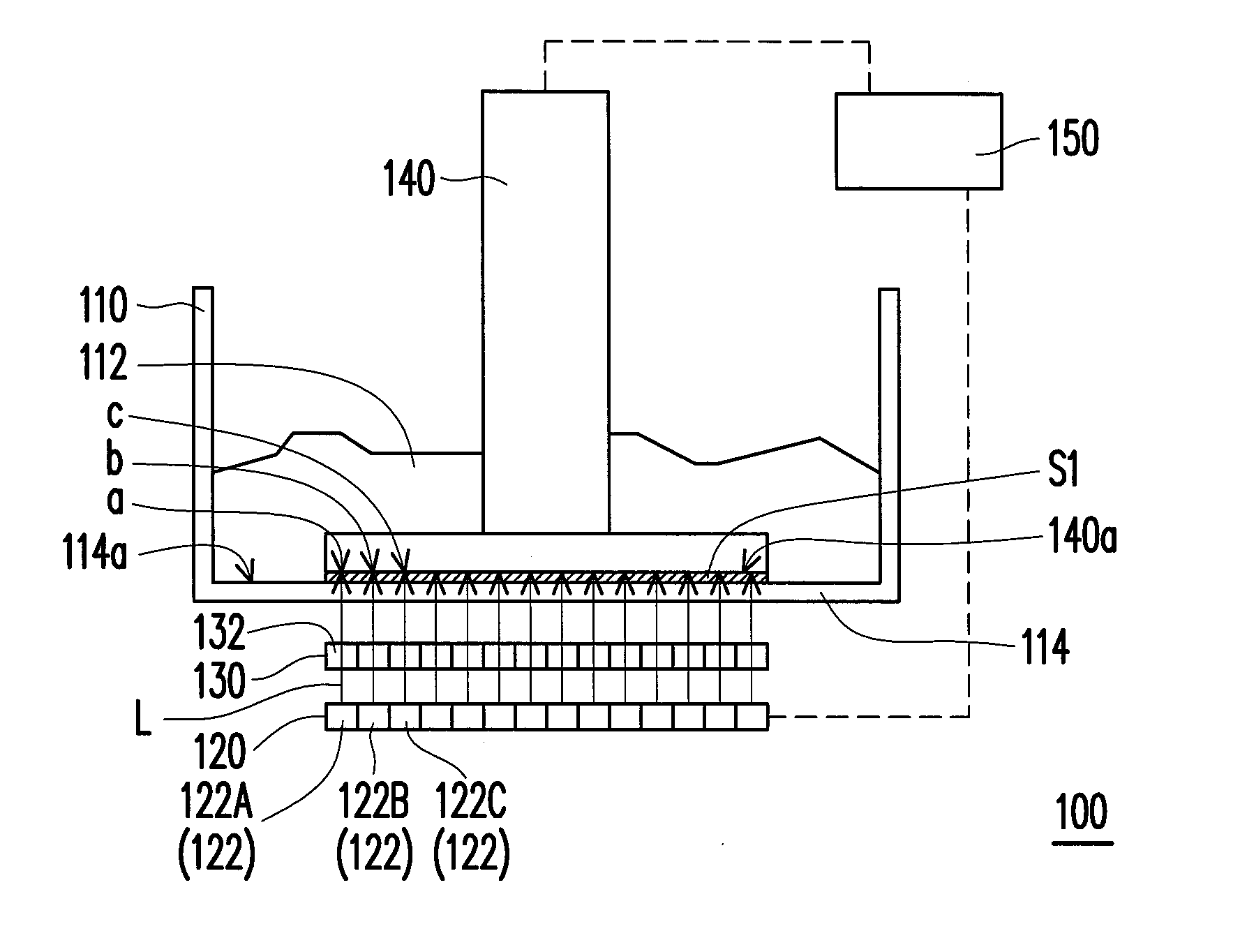
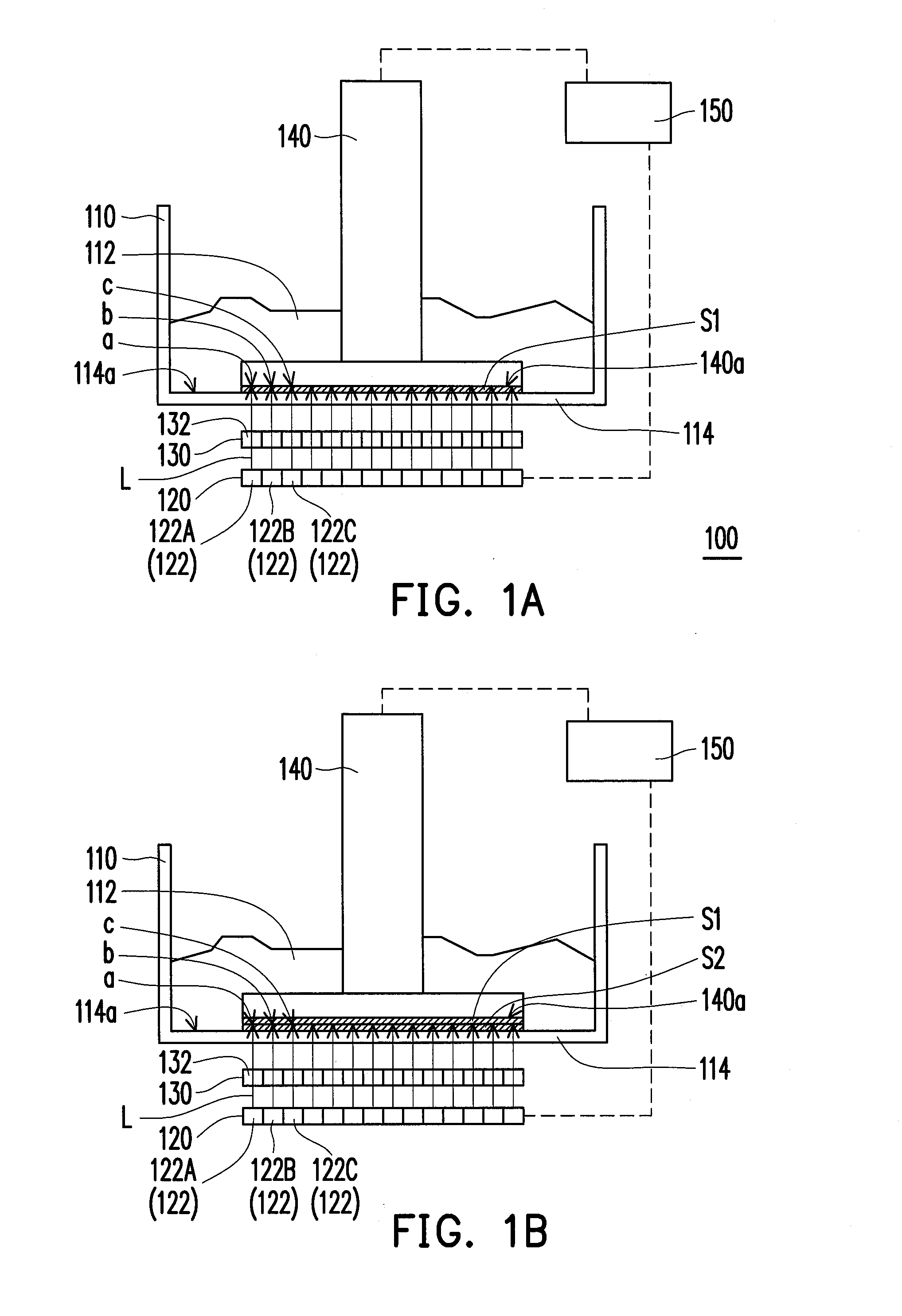
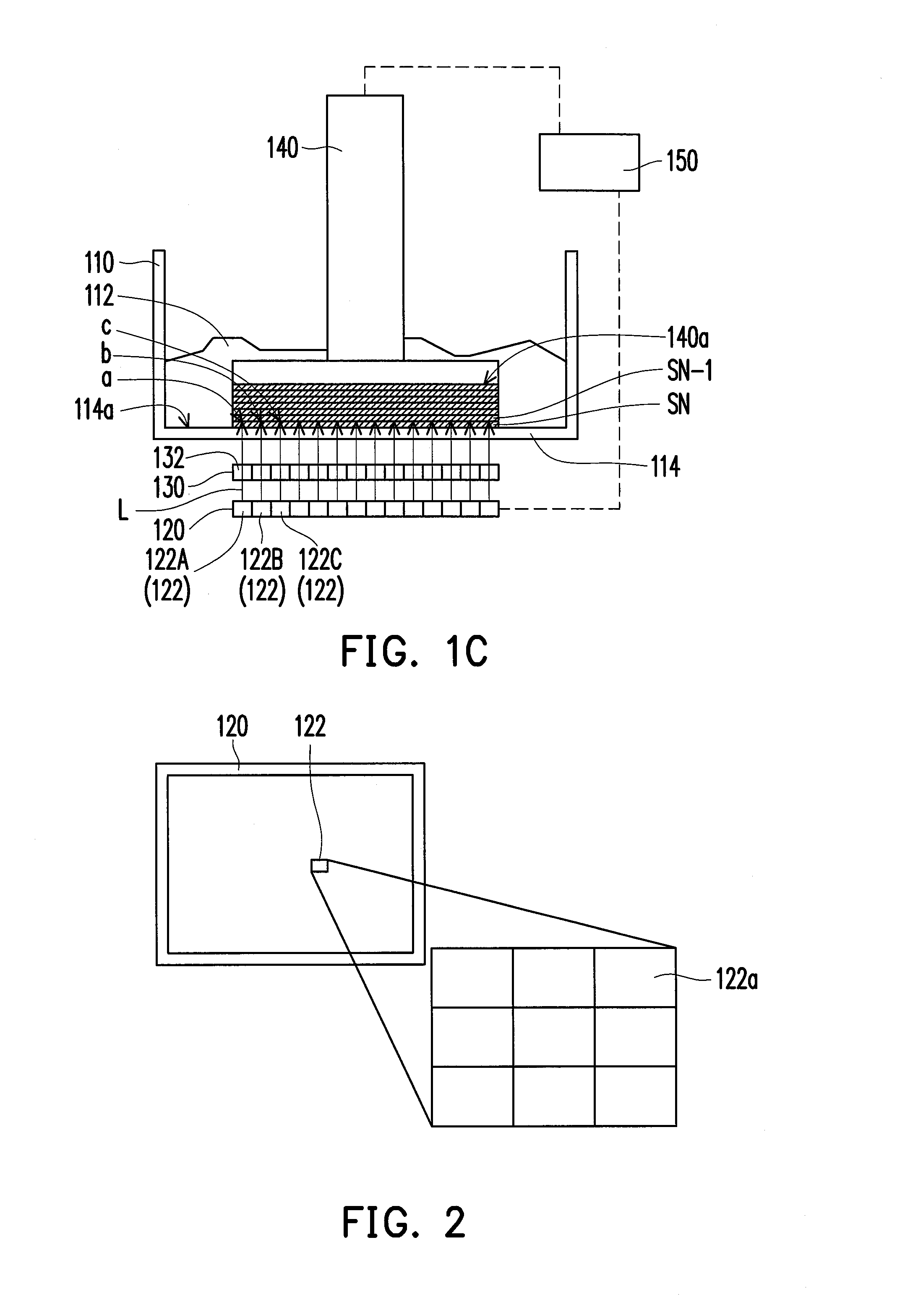
Three-dimensional printing apparatus
a three-dimensional printing and printing machine technology, applied in auxiliary shaping machines, manufacturing tools, additive manufacturing, etc., can solve the problem that the overall size of such systems cannot be miniaturized, and achieve the effect of reducing the overall size of the three-dimensional printing machin
- Summary
- Abstract
- Description
- Claims
- Application Information
AI Technical Summary
Benefits of technology
Problems solved by technology
Method used
Image
Examples
first embodiment
[0052]FIG. 3A illustrates a corresponding relationship between the display units of the display and the optical structures of the optical film in the invention. FIG. 3A is a top view illustrating the overlapping of the display 120 and an optical film 130A, wherein the portion with dotted line surrounded represents the display 120, and the portion with full line surrounded represents the optical film 130A. FIG. 3B is a side view of FIG. 3A.
[0053]Referring to FIG. 3A and FIG. 3B together. In the embodiment, the optical film 130A has a plurality of optical structures 132A, wherein each optical structure 132A is a lens (such as lens having bent surface on both two directions that are perpendicular to each other), a size of each optical structure 132A is substantially equal to the size of each display unit 122.
second embodiment
[0054]FIG. 4A illustrates a corresponding relationship between the display units of the display and the optical structures of the optical film in the invention. FIG. 4B is a side view of FIG. 4A. Each optical structure 132B of the optical film 130B of the embodiment is similar to the optical structure 132A shown in the FIG. 3A, namely, the lens. However, a size of each optical structure 132B is substantially smaller than the size of the display unit 122.
third embodiment
[0055]FIG. 5A illustrates a corresponding relationship between the display units of the display and the optical structures of the optical film in the invention. FIG. 5B is a side view of FIG. 5A. In the embodiment, each optical structure 132C on the optical film 130C is a cylindrical lens, and a width of each optical structure 132C is substantially equal to the width of the display unit 122.
[0056]According to the embodiments in FIG. 3A, FIG. 4A and FIG. 5A, an image of the display units 122 is formed on the photosensitive material 112 through the lens or the cylindrical lens. Therefore, each of the optical structures 132A, 132B and 132C may be adjusted, for aligning with at least one display unit 122. For example, in FIG. 3A, each lens (the optical structure 132A) is aligned with one corresponding display unit 122. In another embodiment, each of the display unit 122 is aligned with a plurality of optical structures. For example, in FIG. 4A, each of the display units 122 is align wit...
PUM
| Property | Measurement | Unit |
|---|---|---|
| Distance | aaaaa | aaaaa |
| Size | aaaaa | aaaaa |
| Transparency | aaaaa | aaaaa |
Abstract
Description
Claims
Application Information
 - R&D
- Intellectual Property
- Life Sciences
- Materials
- Tech Scout
- Unparalleled Data Quality
- Higher Quality Content
- 60% Fewer Hallucinations
Browse by: Latest US Patents, China's latest patents, Technical Efficacy Thesaurus, Application Domain, Technology Topic, Popular Technical Reports.
© 2025 PatSnap. All rights reserved.Legal|Privacy policy|Modern Slavery Act Transparency Statement|Sitemap|About US| Contact US: help@patsnap.com


