OSBS subtractor Accelerator

a subtractor accelerator and step-by-step technology, applied in the field of digital arithmetic circuits, can solve the problem of requiring two addition operations, achieve the effect of reducing the propagation delay of 2 propagation delays, accelerating the subtraction operation, and high number of components

Inactive Publication Date: 2013-11-07
SOHAY LESLIE IMRE
View PDF4 Cites 4 Cited by
  • Summary
  • Abstract
  • Description
  • Claims
  • Application Information

AI Technical Summary

Benefits of technology

[0011]This invention will accelerate the subtraction operation by replacing the ripple carry method with a true parallel carry system. This invention is simultaneously generating all Carry signals for all available Bits, reducing the carry generation time to 2 propagation delays for a subtractor circuit. The number of Bits are used by the subtractor circuit is not limited. For a 64 Bit wide subtractor circuit of this invention will generate all carry signals using only 2 propagation delays time or 2 logic levels. That is 128 times faster than the conventional parallel adder using twos complement subtraction (double addition) with the ripple carry method (256 / 2=128). This acceleration of the subtraction is achievable by utilizing Claim 9, 10 and Claim 11 of the One Step Binary Summarizer circuit, which is eliminating all complement operations, including: double addition, multiple moves, iterative instructions sets for the subtraction operation, and has a capability to subtract the smaller magnitude operand from the larger magnitude operand; regardless which input operand is the Minuend ad which is the Subtrahend, without moving the operands or duplicating the circuitry. Similarly for the Carry Look Ahead Adder circuit, this invention can operate in two different formats: the “Pure” format which requires high number of components, and a grouped format, where the number of components in used are considerably reduced.
[0013]Most computer systems are using a Carry Look Ahead Buffer circuit to accelerate the speed of the adder circuits carry system.

Problems solved by technology

The worst weakness of this system is: it requires two addition operations.

Method used


Image

  • OSBS subtractor Accelerator
  • OSBS subtractor Accelerator
  • OSBS subtractor Accelerator

Examples


Embodiment Construction

[0034]The detailed description set forth below in connection with the appended drawings is intended as a description of presently preferred embodiments of the improvements and is not intended to represent as the only forms in which the improvements may be constructed and / or utilized.

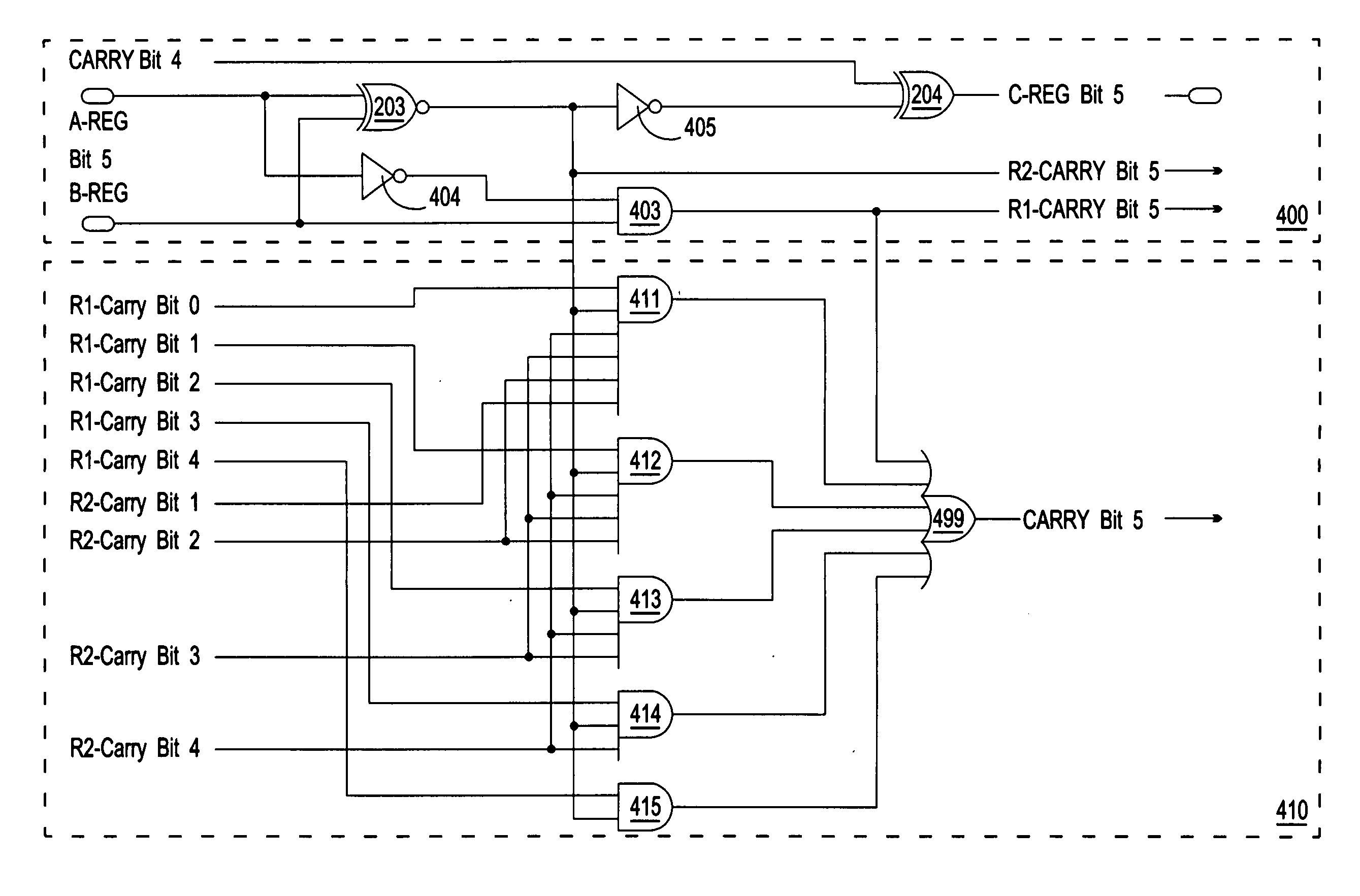
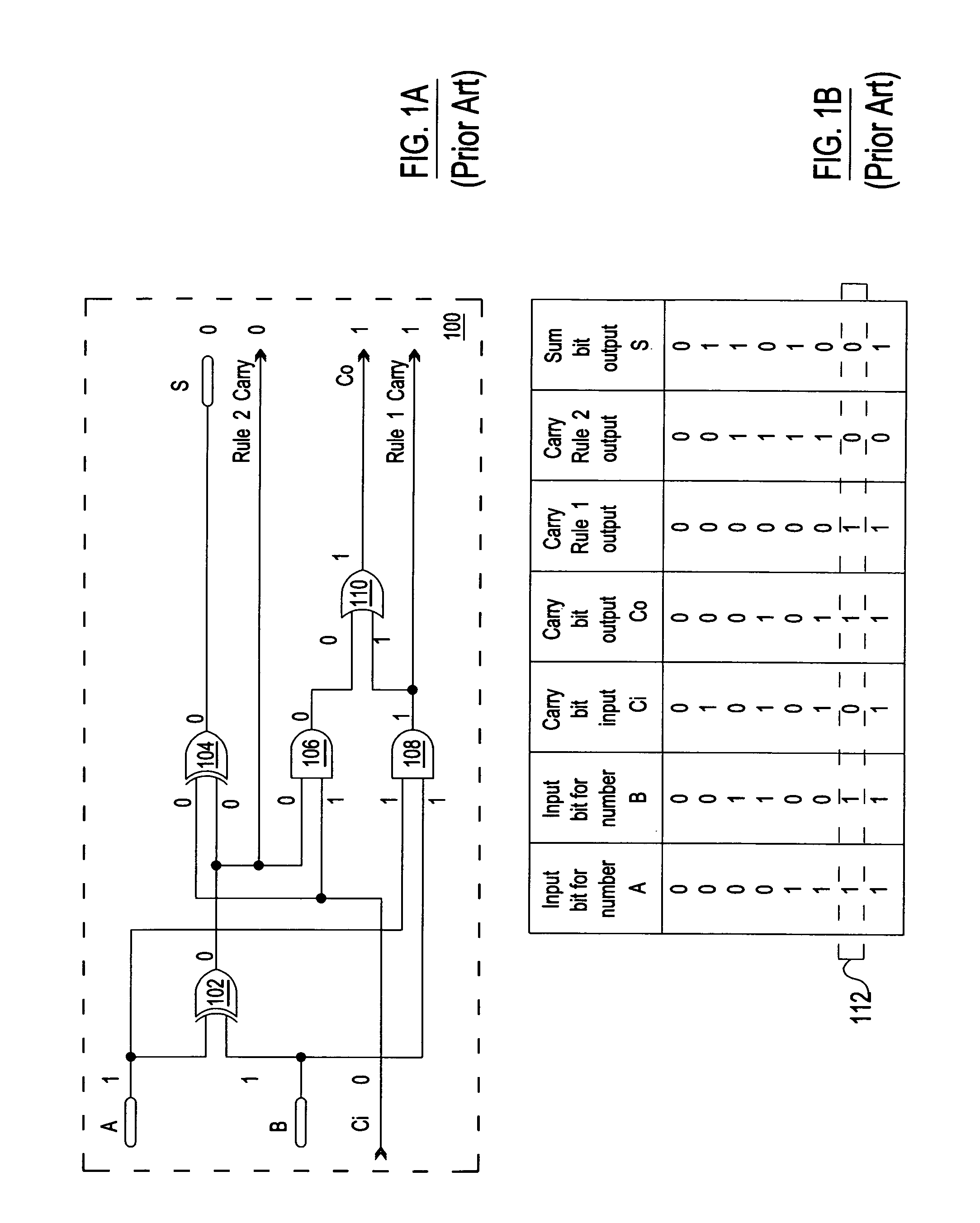
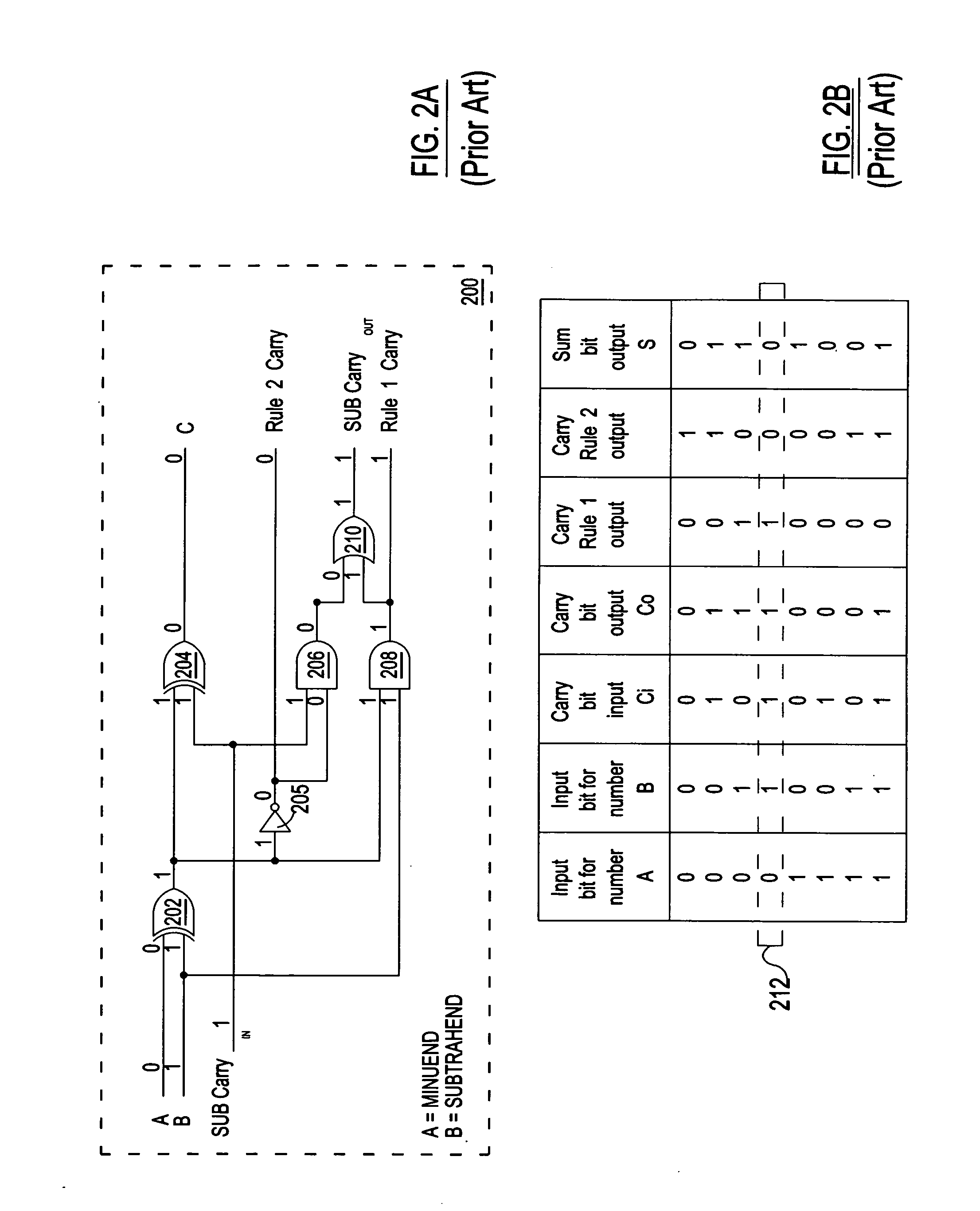
[0035]For purposes of illustration, the various circuit topographies illustrated throughout the disclosure use logic gates, which are symbolic representations of logic functions. The disclosure should not be limited by any specific symbol, logic gate, or any other representation of a logic function, but by the actual logic function itself. Non-limiting examples of logic gates representing logic functions may include AND, NAND, OR, NOR, XOR, XNOR, INV (inverter), or a combination thereof, etc. It should be noted that reference to “first,”“second,”“third, “final” etc. members throughout the disclosure, including the claims, are not used to show a serial or numerical limitation but instead are used to disti...


PUM


Abstract

The OSBS Subtractor Accelerator will enable the subtraction operation to simultaneously subtract all Bits of a data set, where: no ripple affect, no complement operations; therefore no multiple additions, no multiple moves, no temporary storage and no multiple instruction steps are required. In stand alone (pure) format the required time is six propagation delays to perform a subtraction operation. Beside the pure format a distributed or grouped format is available; which is dividing both input operands into groups. This grouped configuration also performs a parallel operation on the bits and on the groups in the same time. However, it needs nine propagation delays to execute a subtraction operation (including the first and second XOR gates); regardless it is a 16, 32 or 64 bit subtractor. It uses considerably less number of components than the pure configuration, and none of the integrated circuits have more than 5 input pins.

Description

BACKGROUND OF THE INVENTION[0001](1) Field of the Invention[0002]The present invention relates to the field of digital arithmetic circuits, more specifically, to the One Step Binary Summarizer (OSBS) circuit.[0003]U.S. Pat. No. 7,991,820[0004]Date: Aug. 2, 2011,[0005]Inventor and owner: Sohay, Leslie Imre (myself).[0006](2) Description of related art[0007]Most of today's computers are performing arithmetic operations, by using an adder circuit. The subtraction can be treated as an addition by the use of complementary numbers (witch includes: double additions, multiple moves, temporary storage).[0008]The subtraction can also be treated as a single addition with the use of the One Step Binary Summarizer's Claim 10“carry concept” method, which is not based on the complementary number system.[0009]FIG. 1A (Prior Art) drawing 100 illustrates a well-known, conventional 1-bit full adder. As illustrated in FIG. 1A drawing 100, a conventional 1-bit full adder is comprised of a “first” XOR lo...

Claims


Application Information

Patent Timeline
Patent Type & Authority Applications(United States)
IPC IPC(8): G06F7/50
CPCG06F7/50
Inventor SOHAY, LESLIE IMRE
Owner SOHAY LESLIE IMRE
Why Eureka
Try Eureka