

Paint drying method
a drying method and paint technology, applied in drying, light and heating equipment, furnace types, etc., can solve the problems of difficulty in out-diffusion of solvent from freshly applied paint, it already takes several hours, etc., and achieves the effect of reducing energy consumption and speeding up the speed of operation
- Summary
- Abstract
- Description
- Claims
- Application Information
AI Technical Summary
Benefits of technology
Problems solved by technology
Method used
Image

Examples
Embodiment Construction
Object, Solution, Advantages
[0005]It is therefore the object of the invention to provide a paint drying method that operates more energy-efficiently and rapidly than the known drying methods.
[0006]The method according to the invention according to claim 1 and an arrangement according to claim 8 is proposed to solve this object.
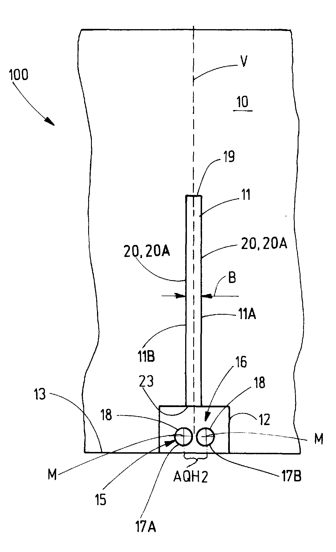
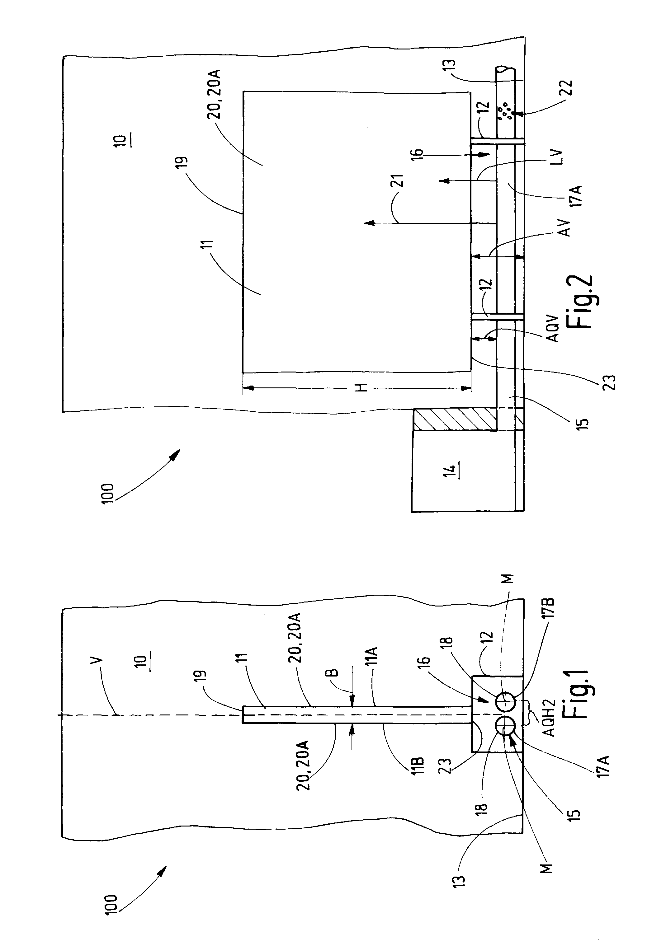
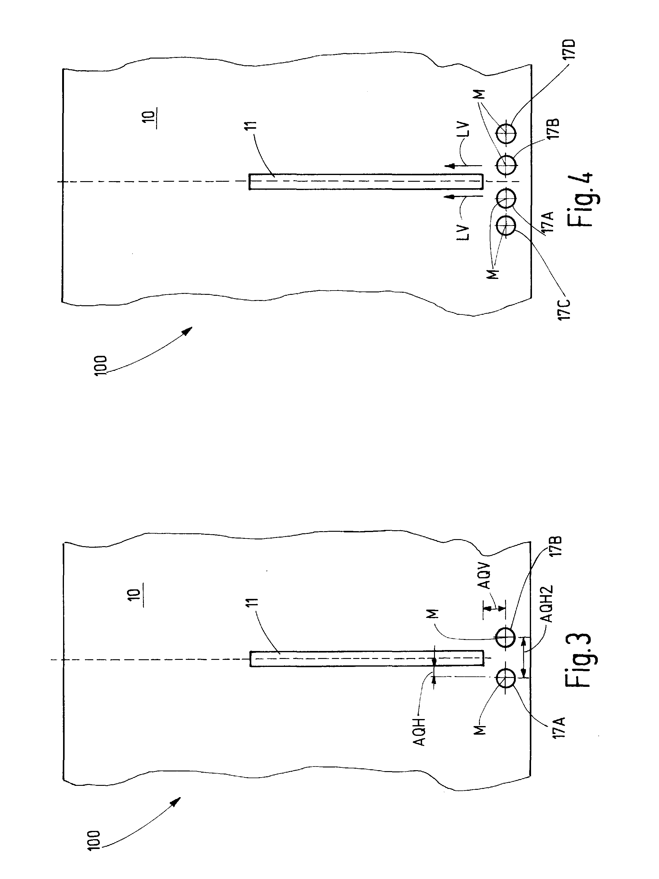
[0007]The method is characterized in that the warm air is supplied with a low momentum at a predefined horizontal distance from the component in the base or fastening or standing region of the component, and in order to achieve and sustain an, in particular surface-related homogenous surface temperature of the component, which in particular is higher than the ambient or room air temperature in the paint shop, is guided by means of thermal flow effects substantially vertically along the component and / or over and along the surface of the component.
[0008]The maximum value of the component surface temperature is limited by the paint system used.
[0009]A component t...
PUM
 Abstract
Description
Claims
Application Information