

Duct rod system for installing an elongated element in a conduit
- Summary
- Abstract
- Description
- Claims
- Application Information
AI Technical Summary
Benefits of technology
Problems solved by technology
Method used
Image

Examples
case b
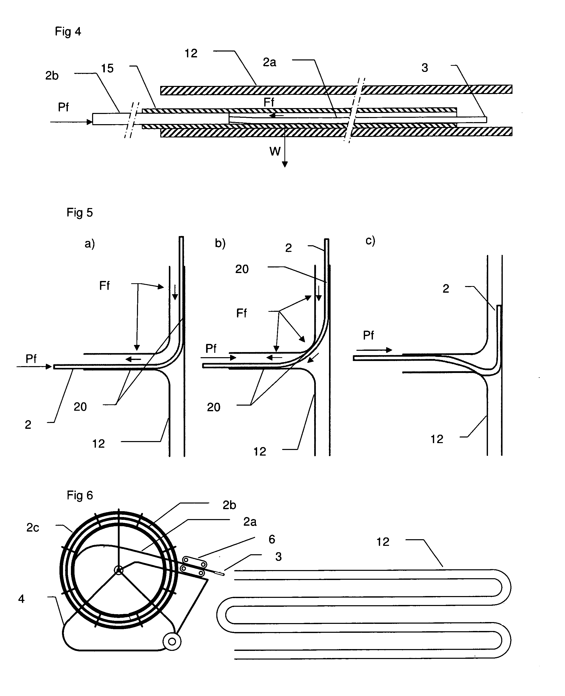
[0040]In case b), the rod 2 inserted into the conduit 12 with a pushing force Pf has a bending stiffness usually too high and as a result contacts the conduit 12 at three contact points 20 in the bending area. At each contact point 20, the bending stiffness makes the rod apply a normal reaction force to the conduit 12 and friction forces Ff appear and act against the movement of the rod in the conduit. The sum of these three resulting friction forces is of course greater than the sum of the two friction forces acting in case a). Here, besides the reaction from the pushing force, also a force resulting from the bending stiffness is adding to the friction.
[0041]In case c), the pushed rod 2 has a bending stiffness too low and has not enough rigidity to correctly pass the bend. Its bending stiffness is not sufficient to prevent the rod from being pushed onto the wall of the conduit 12. In this situation, the rod 2 will buttress onto the wall and the associated friction force will inhibi...
PUM
 Abstract
Description
Claims
Application Information