Method of measuring a physical parameter and electronic interface circuit for a capacitive sensor for implementing the same

a capacitive sensor and physical parameter technology, applied in the direction of capacitance measurement, resistance/reactance/impedence, instruments, etc., can solve the problem of low sensitivity or gain of electronic circuit, variation in measured real force, applied, and supply output signals such as output voltages in analogue form , to achieve the effect of quick supply of stabilised digital measuring signals

Active Publication Date: 2013-11-14
EM MICROELECTRONIC-MARIN
View PDF2 Cites 11 Cited by
  • Summary
  • Abstract
  • Description
  • Claims
  • Application Information

AI Technical Summary

Benefits of technology

[0026]One advantage of the electronic interface circuit for a capacitive sensor lies in the fact that it can quickly provide stabilised digital measuring signals at output as a result of digital processing immediately after the charge transfer amplifier. These digital measuring signals are processed in the logic unit. Two digital signals may be provided dependent on positive biasing and negative biasing of the fixed electrodes of the capacitors. By combining the digital signals this enables any voltage offset to be removed from the electronic circuit components.
[0027]Another advantage of the electronic interface circuit for a physical sensor lies in the fact that the digital-analogue converter includes a resistive divider, each resistive node of which is connected to a multiplexer, which is operated in succession by each binary word stored in a corresponding register of the logic unit. This resistive divider allows the digital...

Problems solved by technology

These stray capacitances do not depend on the motion of the moving electrode, which consequently creates non-linearities and also lowers the sensitivity or gain of the electronic circuit.
Because of the influence of the substrate potential on the electrostatic force, this leads to a variation in the measured real force, which is applied across the common moving electrode, which is a drawback.
However, one drawback of the electronic circuit of EP Patent No 1 835 263 B1 is that it supplies output signals, such as output voltages, in analogue form.
This means that it is not possible to sufficiently reduce the size of the integrated components and the electrical power consumpti...

Method used


Image

  • Method of measuring a physical parameter and electronic interface circuit for a capacitive sensor for implementing the same
  • Method of measuring a physical parameter and electronic interface circuit for a capacitive sensor for implementing the same
  • Method of measuring a physical parameter and electronic interface circuit for a capacitive sensor for implementing the same

Examples


Embodiment Construction

[0031]In the following description, reference will mainly be made to the new method of measuring a physical parameter by means of an electronic interface circuit connected to a capacitive sensor for supplying at least one digital measuring signal at the electronic circuit output.

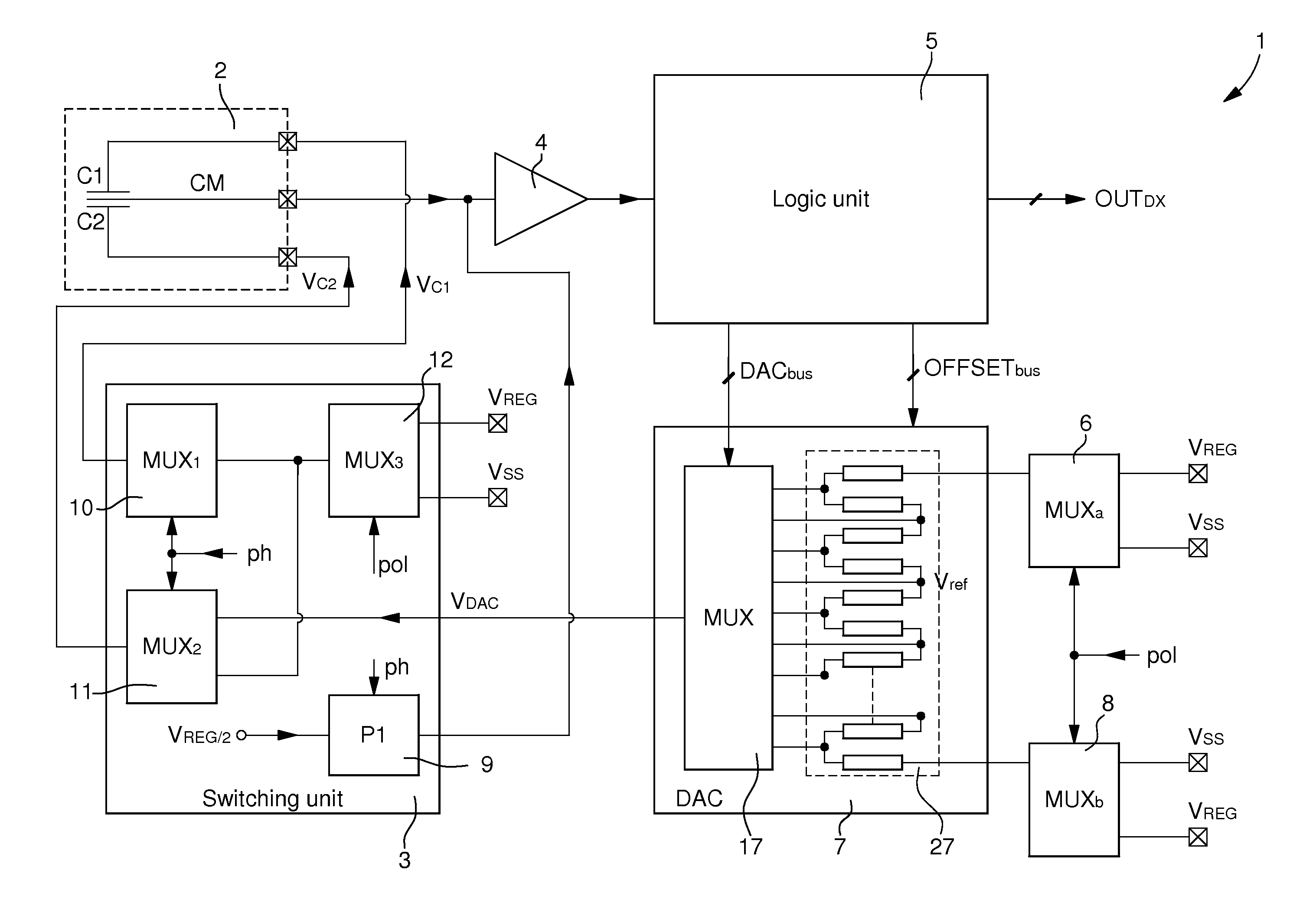
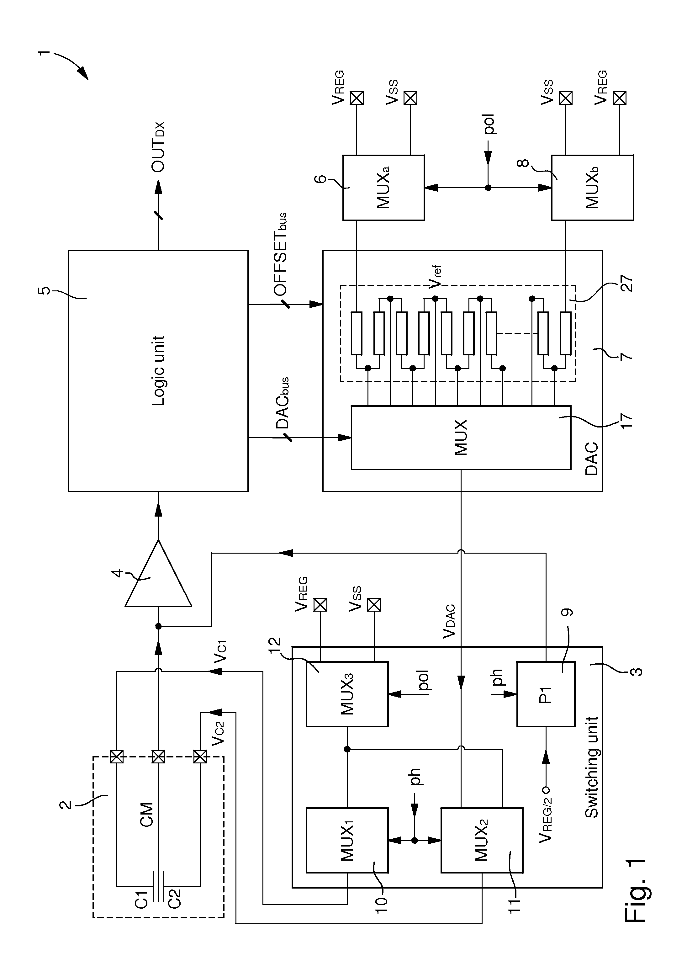
[0032]FIG. 1 shows a simplified diagram of the various components of electronic interface circuit 1 for a capacitive sensor 2 for implementing the physical parameter measuring method according to the invention. In this embodiment, a MEMS capacitive sensor 2 with a single mass is arranged to be connected to electronic circuit 1. This capacitive sensor is thus formed of a pair of capacitors C1 and C2. The two capacitors of each pair are differential connected. A common electrode CM of the pair of capacitors can be moved under the action, in particular, of a force between the two fixed electrodes to perform a physical parameter measurement. Of course, it is also possible to use a tri-axial capacitive sensor, fo...


PUM


Abstract

A physical parameter is measured via an electronic circuit connected to a two capacitor sensor. The circuit includes an amplifier connected to the common capacitor electrode, a logic unit for digital processing amplifier data and supplying a digital measuring signal, a digital-analogue converter for supplying a measuring voltage based on the digital measuring signal, a switching unit for alternately supplying the measuring voltage to the first and second fixed capacitor electrodes, and a regulated voltage for negative biasing or a low voltage for positive biasing from a voltage supply source. A first phase consists in biasing the first fixed electrode with the measuring voltage from first binary word and reference voltage, and the second fixed electrode with low voltage, and a second phase consists in biasing the second fixed electrode with measuring voltage from second binary word, which is reverse of the first binary word, and the reference voltage.

Description

[0001]This application claims priority from European Patent Application No. 12167469.1 filed May 10, 2012 the entire disclosure of which is incorporated herein by reference.FIELD OF THE INVENTION[0002]The invention concerns a method of measuring a physical parameter, such as an acceleration, angular speed, force or pressure, by means of an electronic interface circuit connected to a capacitive sensor.[0003]The invention also concerns an electronic interface circuit for a capacitive sensor for implementing the measuring method. The capacitive sensor is formed of at least two differential connected capacitors. A common electrode of the capacitors is capable of moving between two fixed electrodes under the action, for example, of a force in order to alter the capacitive value of each capacitor.BACKGROUND OF THE INVENTION[0004]In a simple conventional capacitive sensor design, the common electrode, which is mobile, forms part of an armature resiliently held between the two fixed electro...

Claims


Application Information

Patent Timeline
IPC IPC(8): G01R27/26
CPCG01R27/2605G01D5/2403
Inventor GROSJEAN, SYLVAINENTRINGER, CHRISTOPHE
Owner EM MICROELECTRONIC-MARIN
Why Eureka
Try Eureka