3D landscape real-time imager and corresponding imaging methods

a real-time imager and landscape technology, applied in the field of 3d landscape real-time imagers, can solve the problems of limited measurement distance, high cost, and high cost of equipment, and achieve the effect of improving speed, distance and resolution capabilities

Active Publication Date: 2013-11-14
FASTREE3D
View PDF13 Cites 65 Cited by
  • Summary
  • Abstract
  • Description
  • Claims
  • Application Information

AI Technical Summary

Benefits of technology

[0004]Therefore, there is a need for a 3D landscape real-time imager having enhanced speed, distance and resolution capabilities.
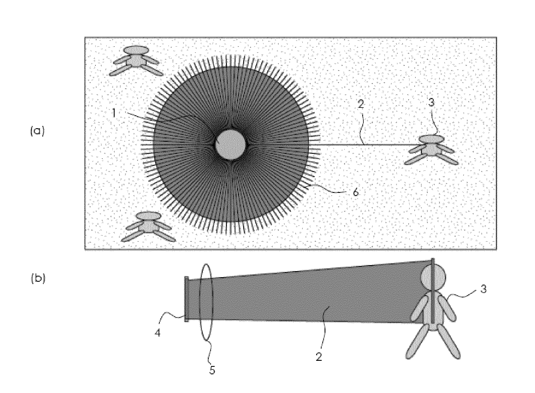
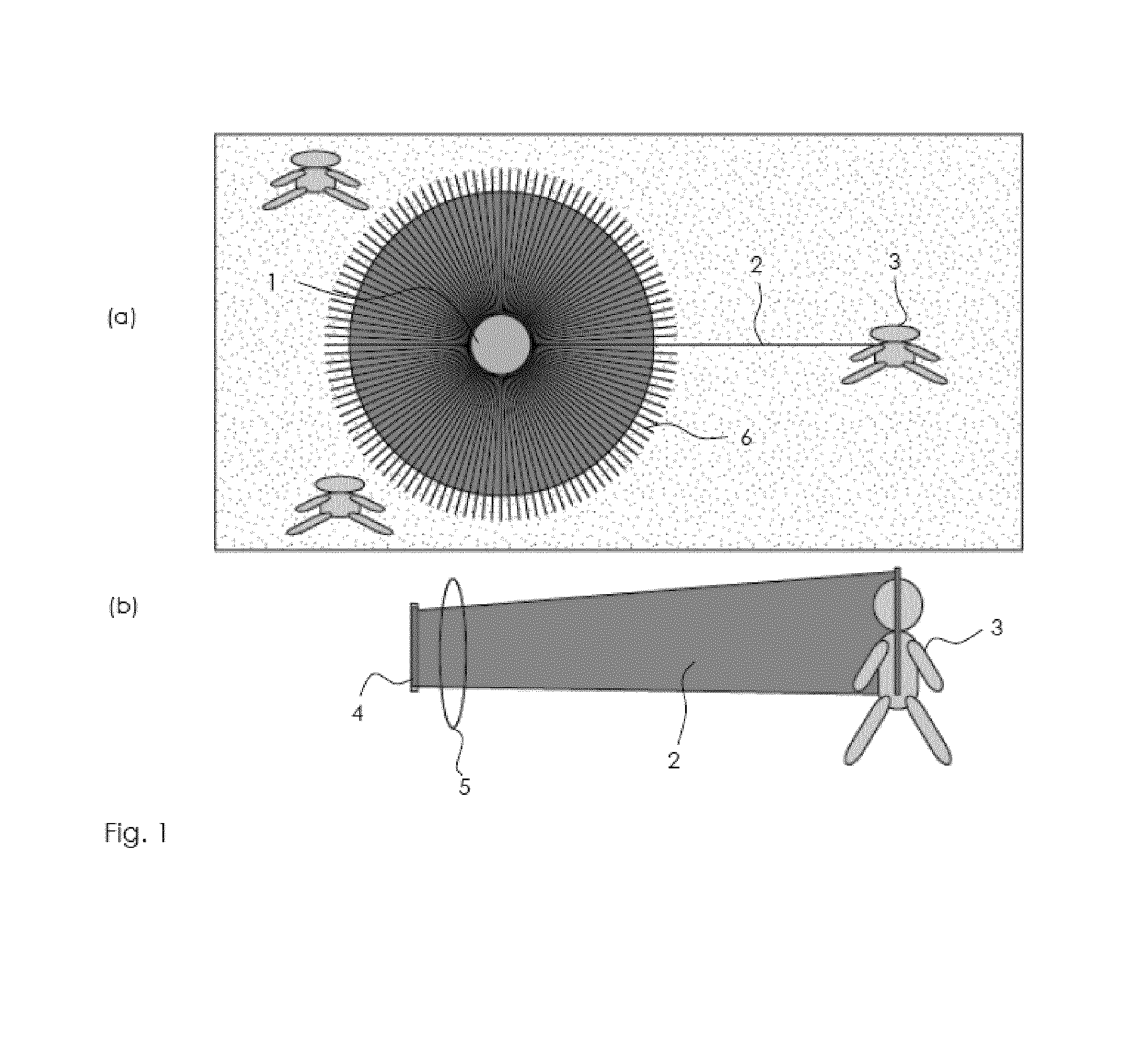
[0012]The present invention also relates to a Set of 3D real-time landscape imagers comprising 3D real-time landscape imagers. Such a set of 3D imagers comprises a central controller and a high-speed data link allows the communication of data streams between them and their central controller such that the 3D landscape imagers coordinate their “launching pulse agenda” to avoid simultaneous pulse reflection from the same targets points.
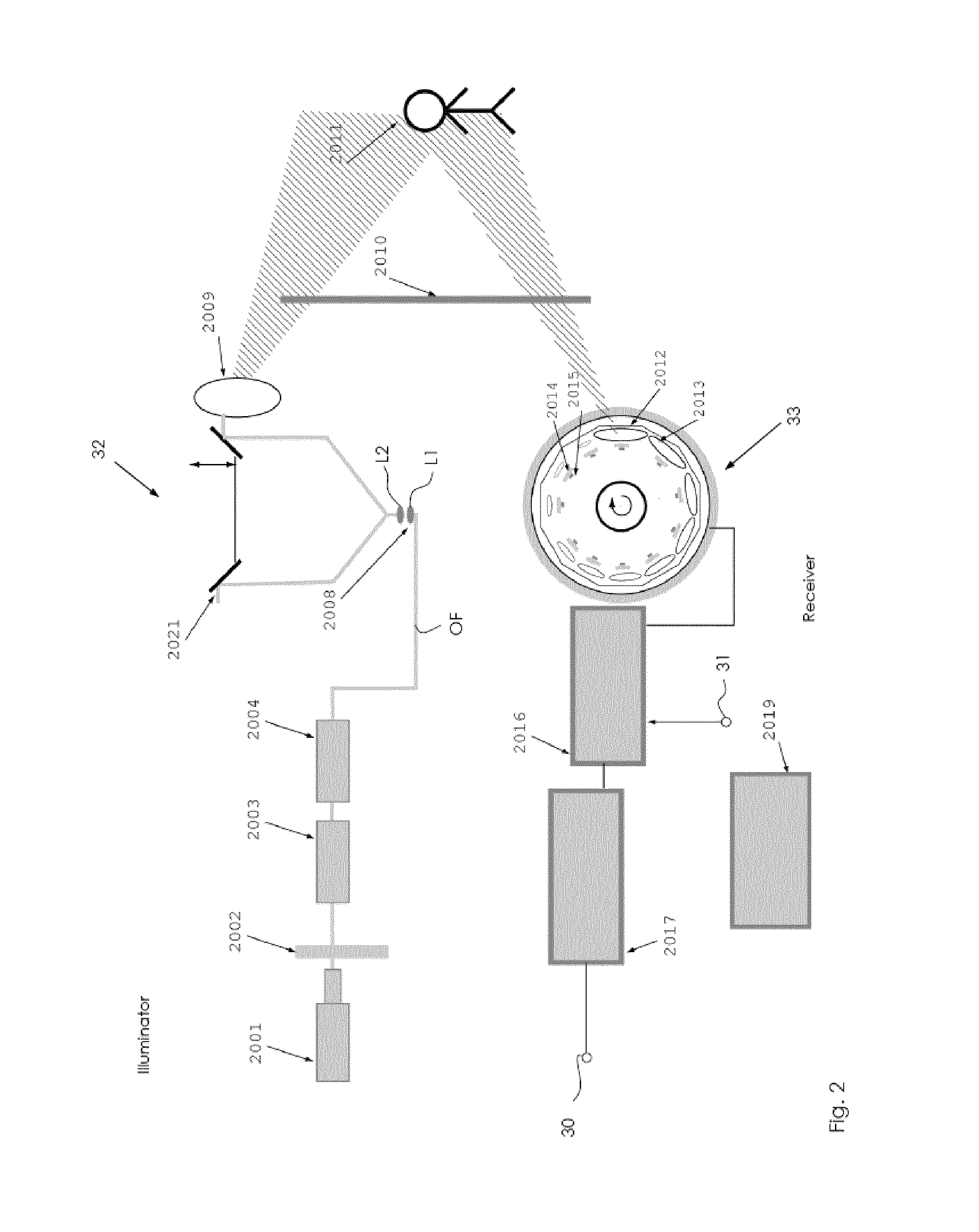
[0018]receiving said reflected pulses onto at least one SPAD detector array, said SPAD detector arrays rotating in synchronism with the emission of said illuminating beams and being arranged to produce detected data on the basis of the measured round-trip delay of the pulses and using the precise timing of the pulse trains for efficiently detecting faint signals at each SPAD detector cell of the said SPAD detector arrays;

Problems solved by technology

They are mostly limited in their characteristics of speed of acquisition and measurement distance.
This limitation arises from the risk of confusion of pulses if multiple pulses are on the way between transmitter and receiver at one time.
Also, high repetition rate pulses may lead to problems if common optics are used for the emission and reception of pulses, because optical elements may cause partial reflections of pulses.
The measurement distance of such devices is limited by the low energy of the pulses they use to maintain eye safety.
Such techniques are not suitable for obtaining fast landscape imaging.
However, it is not possible to generate an image on the basis of such a lidar with a high resolution, at all ranges.
Further, the time to acquire a complete frame of the scene is long, especially when the scanned scene is a complete landscape.

Method used


Image

  • 3D landscape real-time imager and corresponding imaging methods
  • 3D landscape real-time imager and corresponding imaging methods
  • 3D landscape real-time imager and corresponding imaging methods

Examples


Embodiment Construction

[0034]The Detector Used in the 3D Real-Time Landscape Imager

[0035]In another patent application filed the same day by the same applicant and entitled “Methods and devices for generating a representation of a 3D scene at very high speed”, a new device based onto a SPAD detector array has been described. Such a device comprises a plurality of photodiodes operating above the breakdown voltage, known as Single Photon Avalanche Diodes. Such diodes are capable of detecting single photons at very high speed thanks to an avalanching process that provides significant carrier amplification with a timing resolution of a few picoseconds.

[0036]In the aforementioned patent application, a process to build an IR SPAD diode has been described based on a Ge layer which is grown or deposited on a CMOS integrated circuit. The Ge layer is deposited onto a well, the dimensions of which are favorable to trap single and multiple photons at a given wavelength or multiple wavelengths. The SPAD is coupled to ...


PUM


Abstract

A 3D landscape real-time imager, and method for operating such an imager, where the imager includes:at least one illuminating part which is designed to scan at least a portion of the landscape at a given range and having an ultra-short laser pulse source emitting at least one wavelength, and an optical rotating block, with a vertical axis of rotation, and controlled such that given packets of pulses are shaped in a pattern of rotating beams sent toward the at least partial landscape; andat least one receiving part which includes a set of SPAD detector arrays, each arranged along a vertical direction and rotating at a given speed in synchronism with the optical rotating block of the illuminating part, the detection data of the SPAD detector arrays being combined to acquire 3D imaging data of the at least partial landscape in a central controller.

Description

TECHNICAL FIELD[0001]The present invention relates to a 3D landscape real-time imager. It also relates to methods for operating such an imager.BACKGROUND OF THE INVENTION[0002]Some 3D imagers exist today. An example of such a prior art is WO-2009139971 (A2), entitled “COMPUTER VISION-BASED MULTI-TOUCH SENSING USING INFRARED LASERS”. Another patent application US-A-2002033818, entitled “Three-dimensional relative positioning and tracking using LDRI” teaches the use of a laser to illuminate a target and then to acquire an enhancement of the imagery produced on the basis of such an illumination. Such 3D imagers are also described in a textbook entitled ‘Principles of 3D image analysis and synthesis’, Bernd Girod, Günther Greiner, Heinrich Niemann, (Chapter 1.2), Kluwer 2002. Such 3D imagers have a very high depth accuracy. They are mostly limited in their characteristics of speed of acquisition and measurement distance. They all require that no or very few light pulses are emitted befo...

Claims


Application Information

Patent Timeline
Patent Type & Authority Applications(United States)
IPC IPC(8): H04N13/02G01S17/89
CPCH04N13/0253G01S7/4817G01S7/483G01S17/89H04N13/254
Inventor BOROWSKI, ANDRE
Owner FASTREE3D
Why Eureka
Try Eureka