LED lighting apparatus

a technology of led lighting and lighting components, which is applied in the direction of lighting and heating equipment, lighting support devices, coupling device connections, etc., can solve the problems of difficult repair or replacement parts, deterioration of workability, and process of separating electrical cables, so as to improve workability, easy repair and substation of parts, and easy separation

Active Publication Date: 2013-11-14
CELLEGAIN CO LTD
View PDF9 Cites 77 Cited by
  • Summary
  • Abstract
  • Description
  • Claims
  • Application Information

AI Technical Summary

Benefits of technology

[0024]According to the present invention, since the contact terminal connected to the pin to which electricity is supplied directly contacts the LED module, an addition electrical wire for supplying electricity to the LED module is not necessary, and thereby a process for connecting the electrical wire to the LED module and the pin is not needed so that the workability can be enhanced.
[0025]Further, since the contact terminal is provided to the cap, it can be easily separated from and coupled to the cover and the LED module, and thereby repair and substation of parts can be easy so that the product credibility can be enhanced.
[0026]Further, since the contact terminal is provided with the third contact portion, the contact terminal can directly contact the LED module through the third contact portion when the LED module is inserted into the insert hole and at the same time the third contact portion elastically supports the LED module by its elastic force toward the support member so as to fix the LED module so that contact failure due to external influences such as vibration can be prevented.

Problems solved by technology

However, the conventional LED lighting apparatus which adopts a method of the printed circuit board and the pin with the electrical cable has a problem in that a process of separating the electrical cable for the purpose of repair or replacement of parts is complicated or in case of being connected by welding the separation is not easy so as to deteriorate the workability so that it is difficult to repair or replace parts.

Method used


Image

  • LED lighting apparatus
  • LED lighting apparatus
  • LED lighting apparatus

Examples


Embodiment Construction

[0033]Embodiments of the present invention will be described hereinafter with reference to the accompanied drawings.

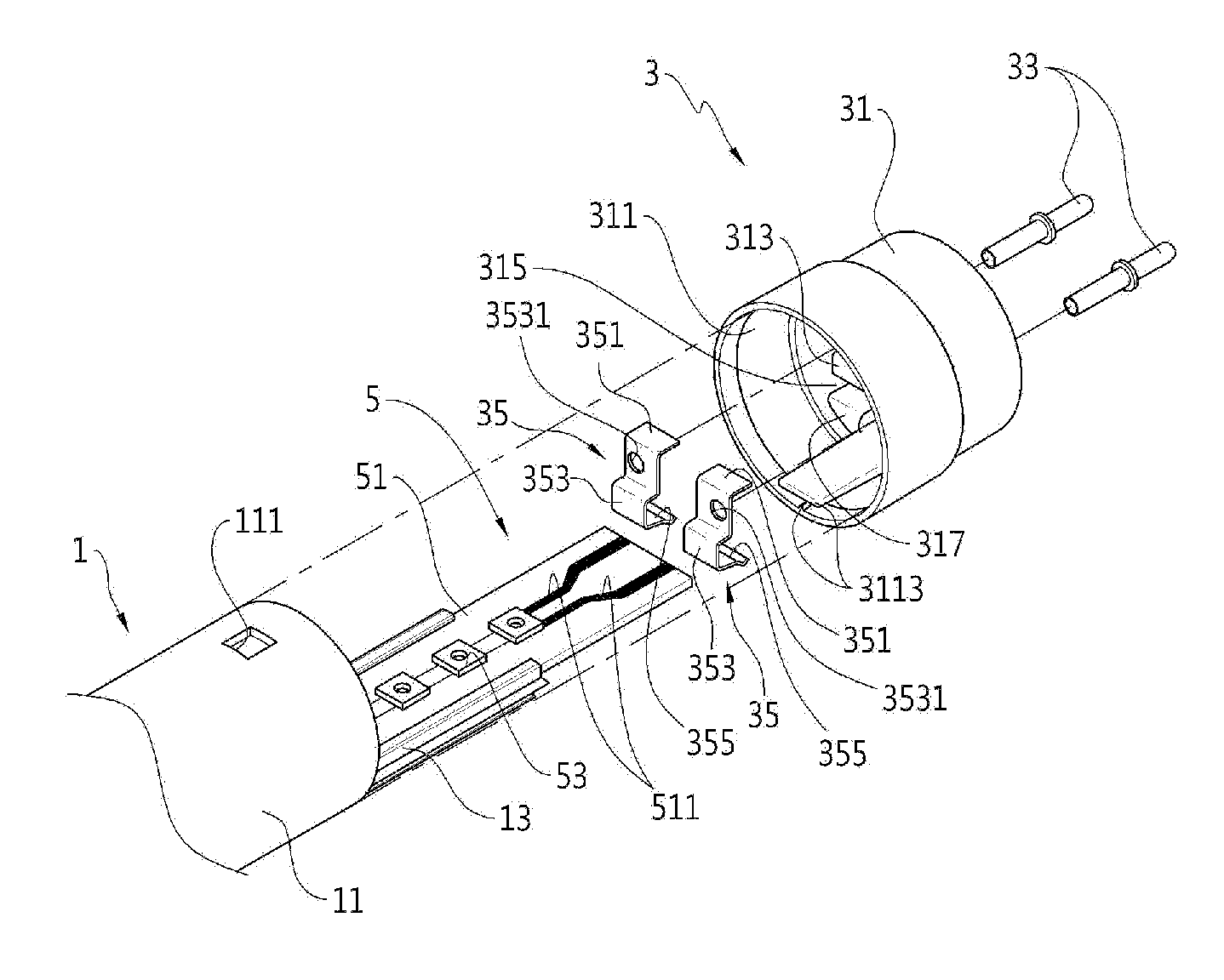
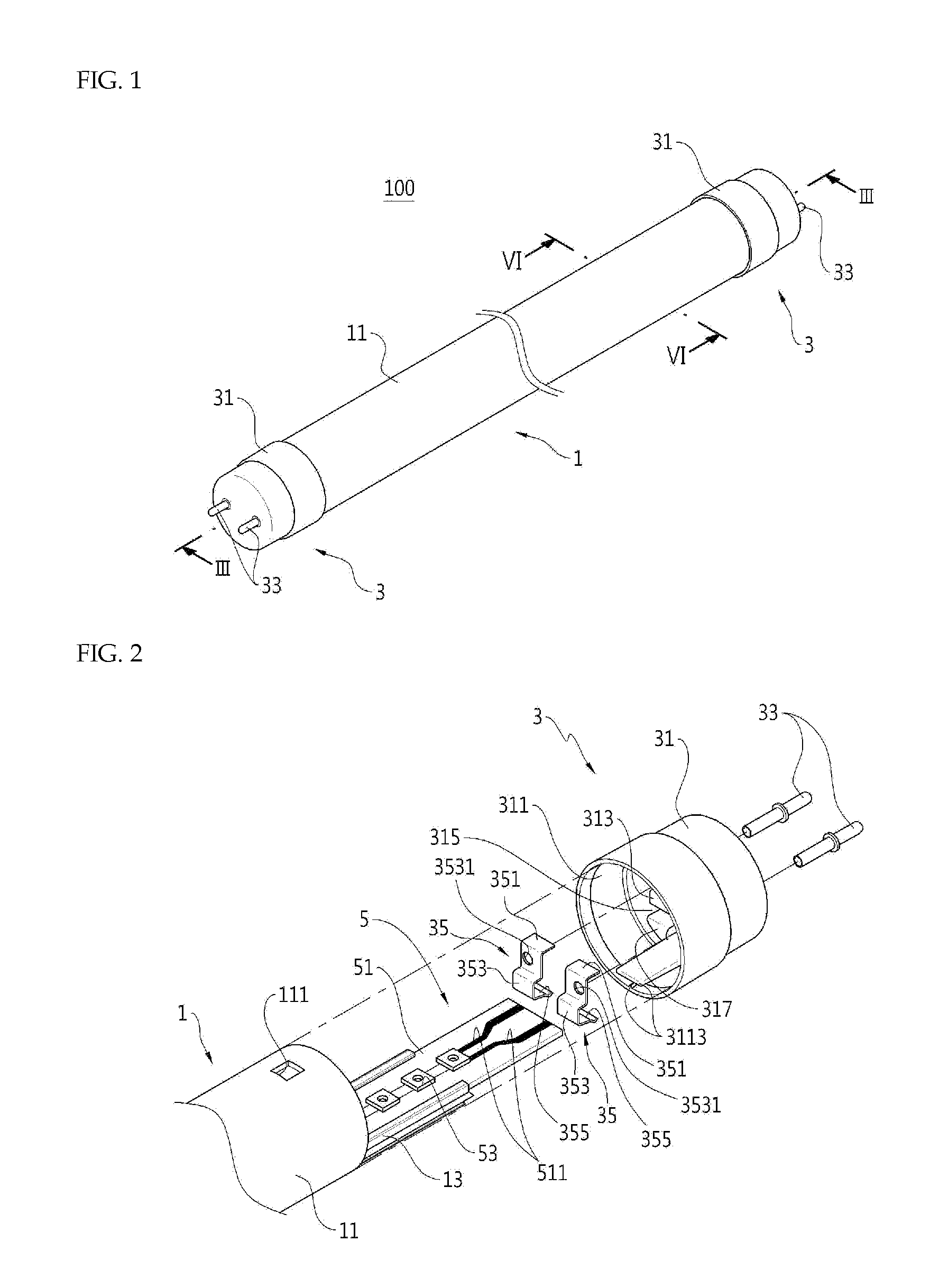
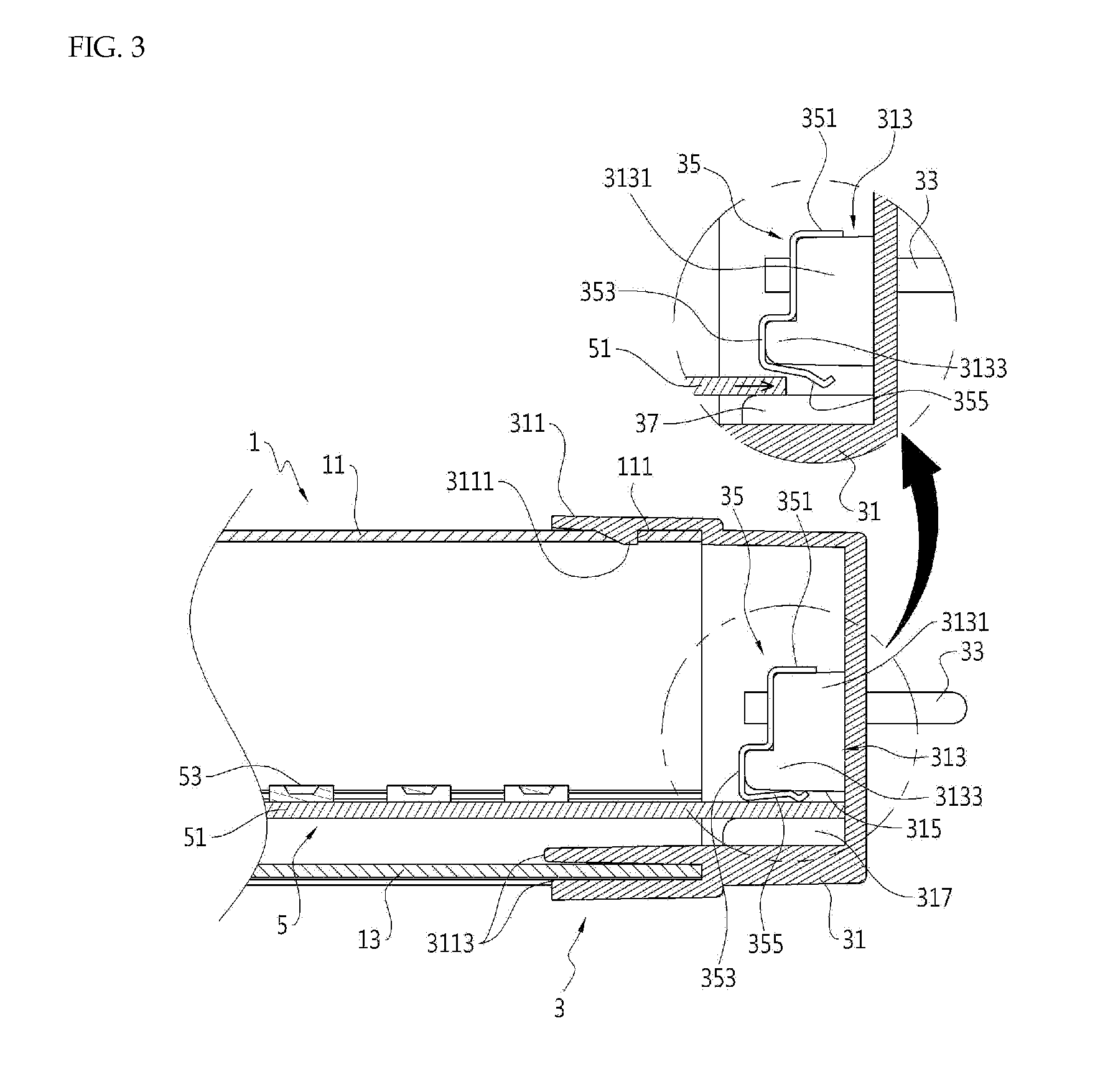
[0034]FIG. 1 is a perspective view of an LED lighting apparatus according to an embodiment of the present invention, FIG. 2 is a partially exploded perspective view of an LED lighting apparatus according to an embodiment of the present invention, FIG. 3 is a sectional view taken along a line III-III in FIG. 1, FIG. 4 is a top view showing an internal structure of a cap of an LED lighting apparatus according to an embodiment of the present invention, FIG. 5 is a cut away perspective view showing an internal structure of a cap of an LED lighting apparatus according to an embodiment of the present invention, and FIG. 6 is a sectional view taken along a line VI-VI in FIG. 1.

[0035]Referring to FIG. 1 and FIG. 2, an LED lighting apparatus 100 according to an embodiment of the present invention (hereinafter referred to as an LED lighting apparatus 100) includes a cover 1, a c...


PUM


Abstract

The light emitting diode lighting apparatus includes: a tubular cover; a cap portion which is coupled to an end of a longitudinal direction of the cover; and a light emitting diode module which is coupled to the cap portion and is disposed within the cover. The cap portion includes: a cap which is coupled with the cover and is provided with a coupling portion therein; and a contact terminal which is coupled to the coupling portion to directly contact the light emitting diode module and elastically supports the light emitting diode module.

Description

CROSS-REFERENCE TO RELATED APPLICATION[0001]This application claims priority to and the benefit of Korean Patent Application No. 10-2012-0048699 filed in the Korean Intellectual Property Office on May 8, 2012, the entire contents of which are incorporated herein by reference.FIELD OF THE INVENTION[0002]The present invention relates to an LED lighting apparatus using a light emitting diode device.BACKGROUND ART[0003]An LED lighting apparatus is a lighting apparatus which is provided with an LED module inside a light transmitting cover and emits light by applied electrical power.[0004]As the invention disclosed in Korean Utility Model publication No. 2011-0012044, in the prior art a printed circuit board of an LED module and pins through which outer electric power is applied are connected to one another by an electrical cable with a predetermined length. In more detail, in the prior art the LED lighting device in which a method of connecting the pins and the printed circuit board with...

Claims


Application Information

Patent Timeline
Patent Type & Authority Applications(United States)
IPC IPC(8): F21K99/00
CPCF21K9/17F21V23/06H01R12/721H01R13/2442F21Y2103/10F21Y2115/10F21K9/27F21V17/00F21V21/002
Inventor KIM, HA-CHULCHONG, HWA-GUNE
Owner CELLEGAIN CO LTD
Why Eureka
Try Eureka