
Radio base station, user terminal and radio communication method

Inactive Publication Date: 2013-11-14
NTT DOCOMO INC
View PDF4 Cites 18 Cited by
  • Summary
  • Abstract
  • Description
  • Claims
  • Application Information

AI Technical Summary

Benefits of technology

The patent describes a way for a radio base station to measure the quality of a network connection by sending a specific pattern of signals. The user terminal measures this pattern using a reference time. This allows for accurate measurements even when different network configurations are used. The technical effect of this patent is improved accuracy and flexibility in measuring network quality.

Problems solved by technology

Considering this handover of the macro UE to the micro cell, the macro UE handed over to the micro base station suffers from large interference from the macro base station and cannot measure quality of the micro base station.

Method used


Image

  • Radio base station, user terminal and radio communication method
  • Radio base station, user terminal and radio communication method
  • Radio base station, user terminal and radio communication method

Examples


embodiment 1

[0026]In this embodiment, it is assumed that in the HetNet having a network configuration where a macro cell overlays a micro cell that is smaller than the macro cell, the micro cell is an OSG (Open Subscriber Group) cell (pico cell).

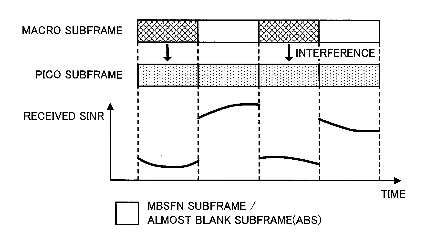
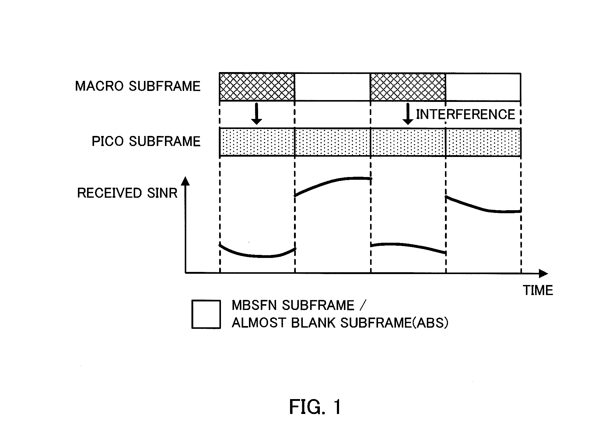
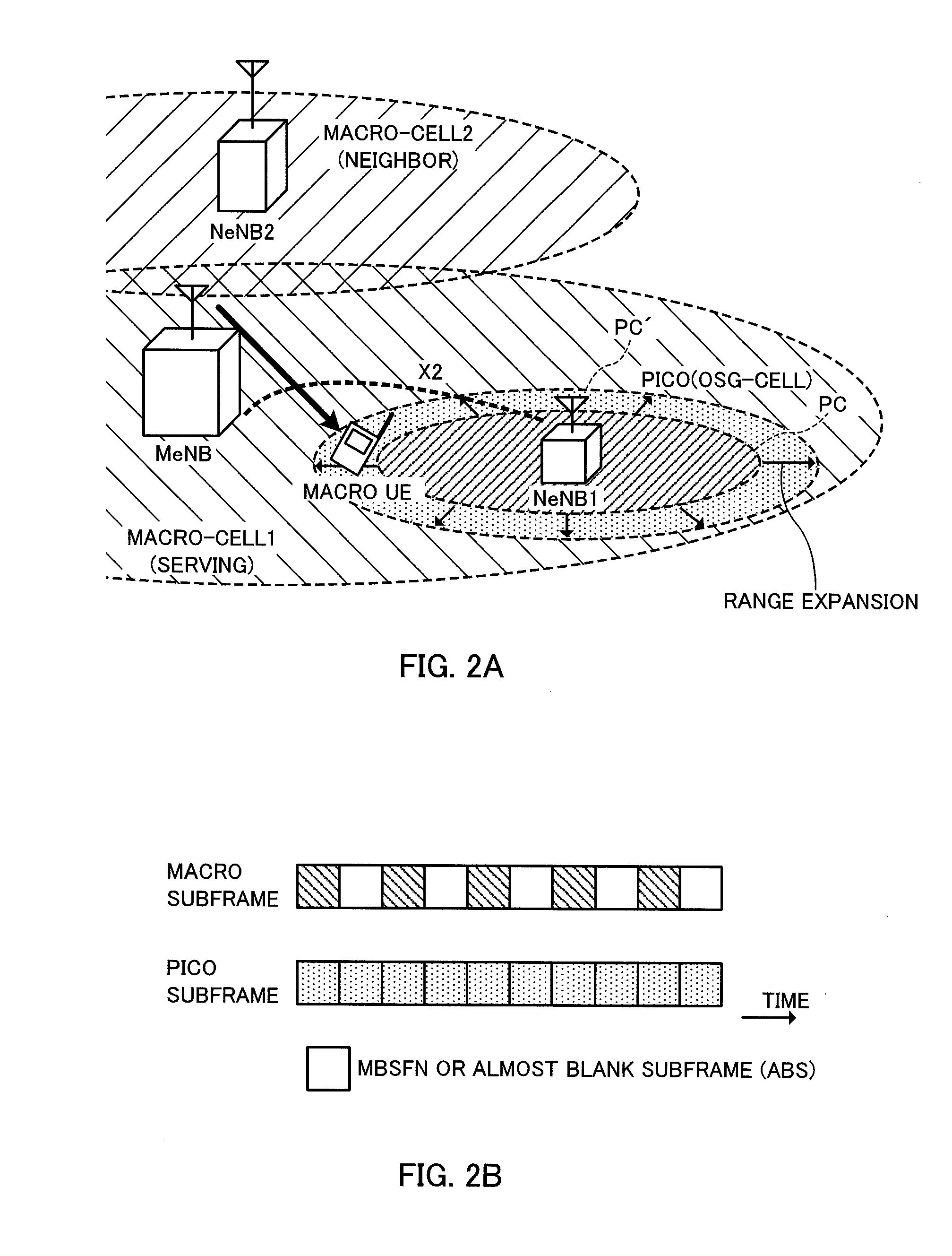
[0027]FIG. 2A is a schematic diagram illustrating the configuration of a radio communication system to which a radio communication method according to the embodiment 1 of the present invention is applied, and FIG. 2B is a diagram illustrating a subframe pattern when the interference coordination is applied.

[0028]In the radio communication system illustrated in FIG. 2A, the macro cell 1 overlays the micro cell (pico cell) as a neighbor cell to the macro cell. And, there exists a macro cell 2 as a neighbor cell to the macro cell 1. The macro cell 1 is a cell formed by a radio base station (macro base station) MeNB, the pico cell as a neighbor cell is a cell formed by a radio base station (neighbor base station:pico base station) NeNB1, and the macro cell ...

embodiment 2

[0049]In this embodiment, it is assumed that in the HetNet having a network configuration where a macro cell overlays a micro cell that is smaller than the macro cell, the micro cell is a CSG (Closed Subscriber Group) cell (femto cell).

[0050]FIG. 4A is a schematic diagram illustrating the configuration of a radio communication system to which a radio communication method according to the embodiment 2 of the present invention is applied, and FIG. 4B is a diagram illustrating a subframe pattern when the interference coordination is applied.

[0051]In the radio communication system illustrated in FIG. 4A, the macro cell 1 overlays the micro cell (femto cell) as a neighbor cell to the macro cell. And, there exists a macro cell 2 as a neighbor cell to the macro cell 1. The macro cell 1 is a cell formed by a radio base station (macro base station) MeNB, a pico cell as a neighbor cell is a cell formed by a radio base station (adjacent base station:femto base station) NeNB1, and the macro cel...


PUM


Abstract

Provided are a radio base station, a user terminal and a radio communication method capable of making accurate measurement in various network configurations in HetNet. The radio communication method according to the present invention has, in a heterogeneous network having a network configuration where a macro cell overlays a micro cell that is smaller than the macro cell, a radio base station that forms the macro cell and is connected to a macro terminal under control of the macro cell determining a measurement subframe to measure a CRS based on the network configuration, generating a time reference indicating the measurement subframe and transmitting a signal including the time reference and the CRS to the macro terminal; and the macro terminal receiving the time reference and the CRS and measuring the CRS in the measurement subframe indicated by the time reference.

Description

TECHNICAL FIELD[0001]The present invention relates to a radio base station, a user terminal and a radio communication method in a radio communication system where a micro cell is provided in a macro cell.BACKGROUND ART[0002]There has been defined in the standards organization 3GPP a radio communication system employing an LTE (Long Term Evolution) scheme (hereinafter referred to as “LTE system”) as a successor system to the UMTS (Universal Mobile Telecommunications System). Now in 3GPP, a radio communication system employing an LTE-Advanced scheme (hereinafter referred to as “LTE-A system”) has been under study as a successor system to the LTE system.[0003]In the LTE-A system, there has been studied HetNet (Heterogeneous Network) in which a micro cell (for example, pico cell or femto cell) having a local coverage of about several-ten-meter radius is formed in a macro cell having a wide coverage of several-kilometer radius (for example, see Non Patent Literature 1).[0004]In such HetN...

Claims


Application Information

Patent Timeline
IPC IPC(8): H04W24/10
CPCH04W24/10H04L5/0007H04L5/0053H04L5/0057H04L5/006H04L5/0073H04W84/045
Inventor ABE, TETSUSHIIWAMURA, MIKIOMIKI, NOBUNIKOTAKAHASHI, HIDEAKI
Owner NTT DOCOMO INC
Learn More