Structure Improvement Of Orthopaedic Implant

US20130304222A1Active Publication Date: 2013-11-14UNITED ORTHOPEDIC CORP

Image

  • Structure Improvement Of Orthopaedic Implant
  • Structure Improvement Of Orthopaedic Implant
  • Structure Improvement Of Orthopaedic Implant

Examples


Embodiment Construction

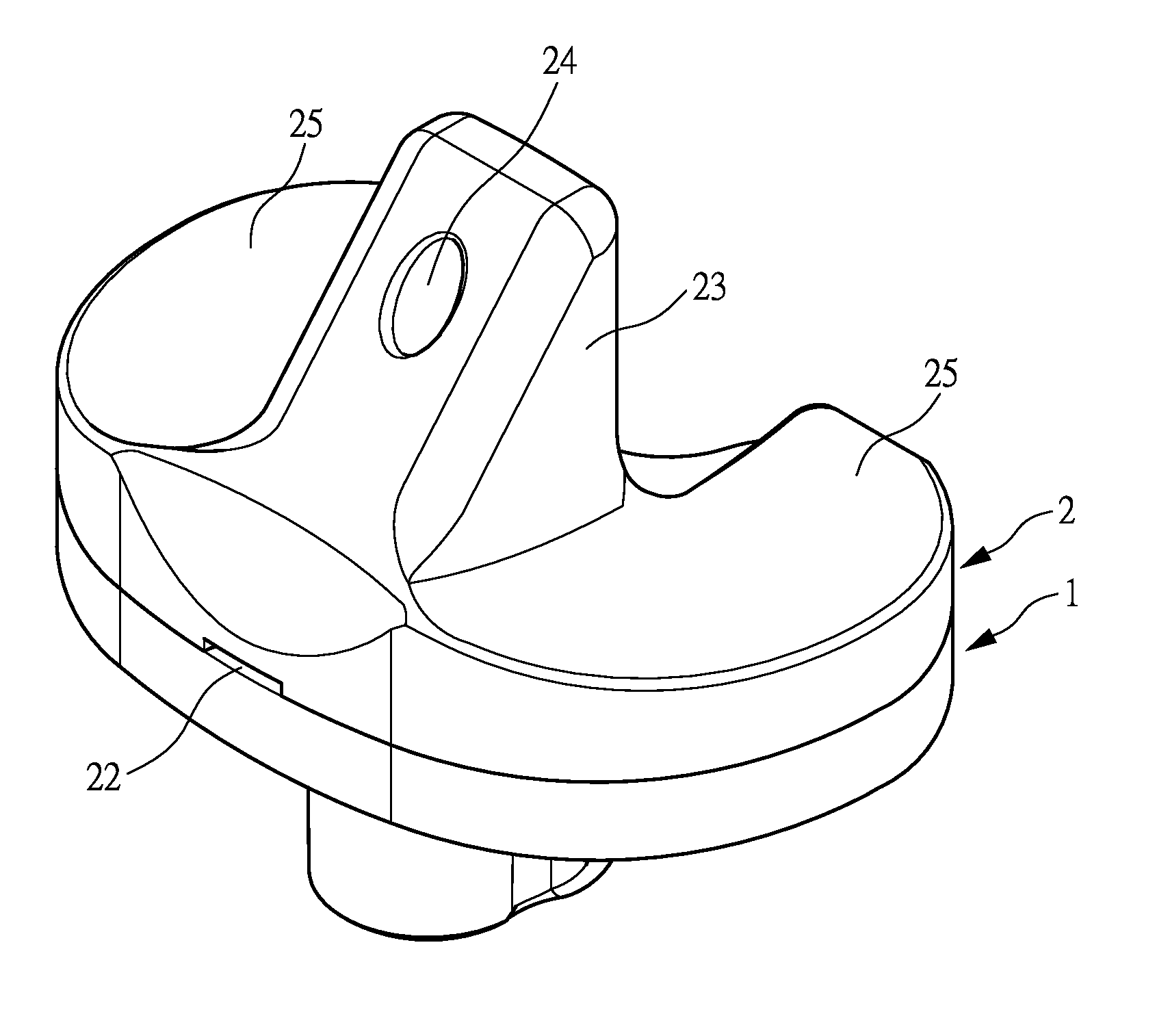
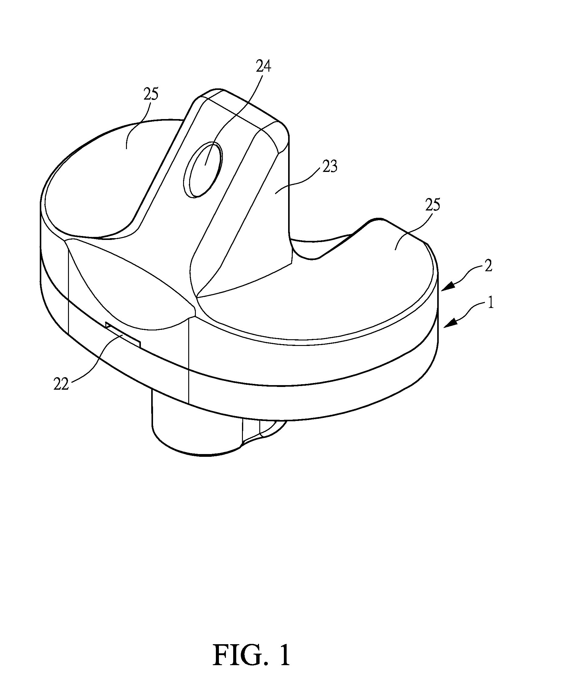
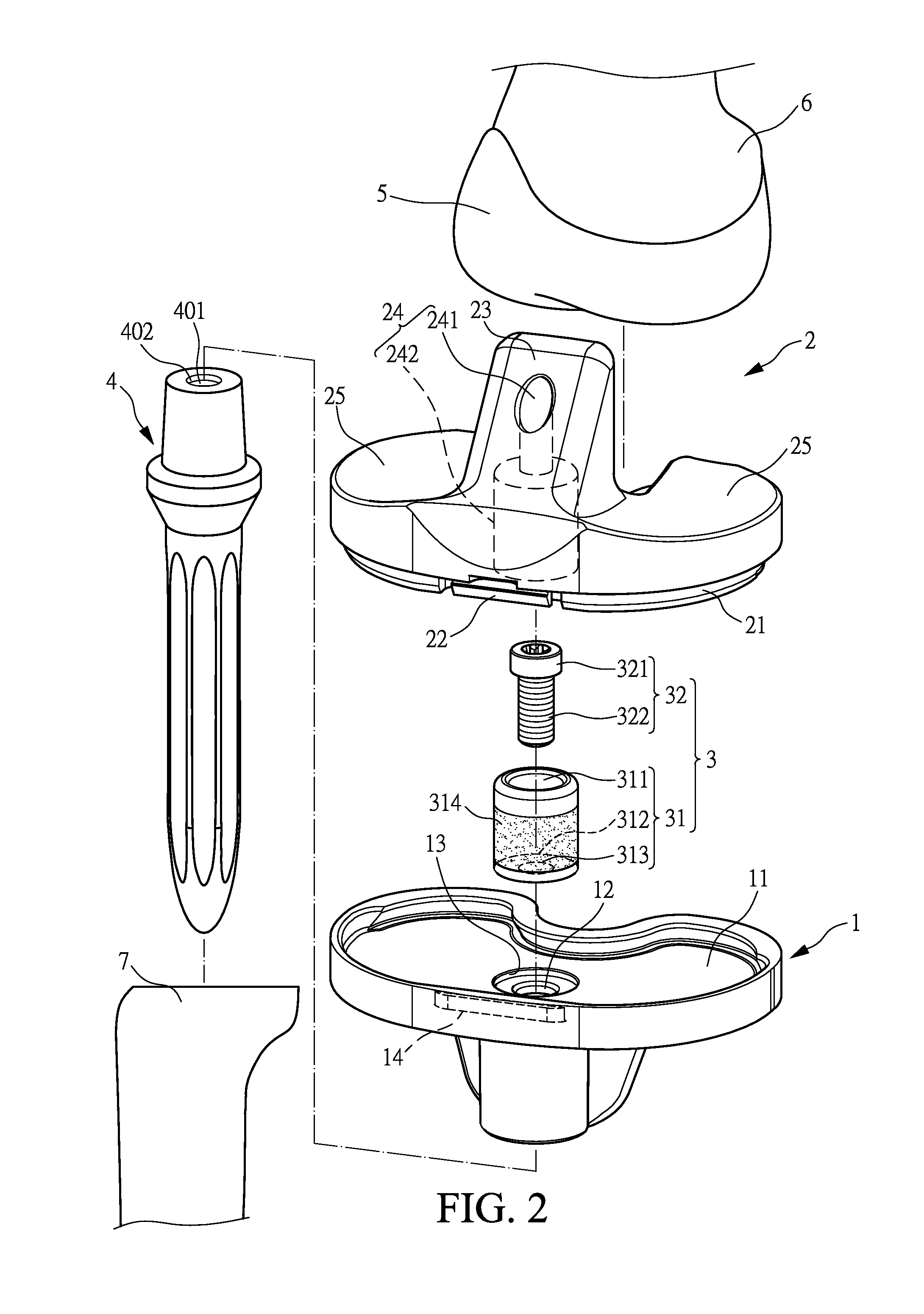
[0018]With reference to the drawings and in particular to FIGS. 1-3, which show, respectively, a perspective view, an exploded view, and a cross-sectional view of an orthopaedic implant constructed in accordance with the present invention, the orthopaedic implant of the present invention connected a femur 6 and a tibia 7, and a stem 4 was implanted into the tibia 7, wherein an end of the stem 4 formed a coupling hole 401 with inner thread 402, inwhich formed to allow inter-engagement between the stem 4 of the tibia 7.

[0019]The orthopaedic implant of the present invention comprises a tibial baseplate 1, a tibial insert 2, and a reinforcement 3.

[0020]The tibial baseplate 1 is of a modular design having various sizes and forms a recess 11. The recess 11 has a bottom that has a central portion defining a through hole 12 extending through the tibial baseplate, and an end of the stem 4 is inserted in the through hole 12 (see FIG. 6), and the through hole 12 has a top circumference that de...


PUM


Abstract

A structure improvement of orthopaedic implant for connecting a distal femur and a proximal tibia, and a stem was implanted into the proximal tibia, inwhich formed to allow inter-engagement between the stem of the tibia and the structure improvement of orthopaedic implant. The structure improvement of orthopaedic implant includes a tibial baseplate, a tibial insert, and a reinforcement. The tibial baseplate forms a recess having a bottom that has a central portion defining a through hole extending through the tibial baseplate. The tibial insert includes a support, a through region, and a projection, wherein an end of the tibial insert forming the projection corresponding to the recess of the tibial baseplate for press-fitting to the tibial baseplate. The reinforcement is inset in the tibial insert and includes a sleeve and a bolt. As such, the advantages of stable coupling includes force resistance, avoids insert loosening then extends prosthetic longevity.

Description

FIELD OF THE INVENTION[0001]The present invention relates to a structure improvement of orthopaedic implant of knee joint, and in particular to an orthopaedic implant comprising a special design of reinforcement to enhance stable coupling between a poly tibial insert and a metal tibial baseplate to offer the advantages of resistance against external force, prevention of deformation, and extension of lifespan, and to be applicable to severe bone damage or revision knee surgery.BACKGROUND OF THE INVENTION[0002]Due to aging, joints of human beings may suffer wear or degradation caused by long term use or degeneration, leading to pain or incapability of providing proper moving functions, as a consequence of which daily living is affected. When a joint suffers severe pathological changes, artificial knee joint replacement provides a measure to release the pain and improve joint function. Artificial knee joint is often composed of components made of metal or plastics and can be fixed to b...

Claims


Application Information

Patent Timeline
14 Nov 2013
Publication
US20130304222A1
IPC
A61F2/38
CPC
A61F2/3868; A61F2/3886; A61F2/389
Inventors
LIU, YU-LIANG; LU, CHENG-KUANG