Lightweight transparent armor window

a transparent, armor window technology, applied in protective equipment, transportation and packaging, synthetic resin layered products, etc., can solve the problems of high cost per square inch of these systems, and inability to meet the requirements of large-scale production

Active Publication Date: 2013-11-21
ORAN SAFETY GLASS INC
View PDF4 Cites 17 Cited by
  • Summary
  • Abstract
  • Description
  • Claims
  • Application Information

AI Technical Summary

Benefits of technology

[0002]Commercially available, glass-based transparent armor typically consists of multiple glass and polymer layers, which are laminated together to form a relatively thick composite. The resulting composite must be transparent and essentially free of optical distortion while providing maximum protection against ballistic impact of projectiles and fragments at minimum weight and minimum cost. Of particular interest are transparent laminates, which restrict the destruction caused by the projectile locally to ensure maximum residual vision and provide protection against multiple hits.
[0008]Present State-of-the-Art glass-based systems provide single-hit protection against armor piercing projectiles (STANAG Level 3 or similar) at oblique impact at areal densities of about 30 psf. In comparison to other glass-based impact-resistant laminates, the designs disclosed provide multi-hit protection against 0.30 cal. AP-M2 or similar projectiles at impact speeds of up to 2750 fps at a thickness of less than 80 mm and an areal density of less than 30 psf. Single-hit protection against the same threat is achievable at an areal density of less than 25 psf by removing one of the glass ceramic layers. The composites are useful, for example, as transparent armor structures in military and security vehicles as well as for windows in secured buildings applications.
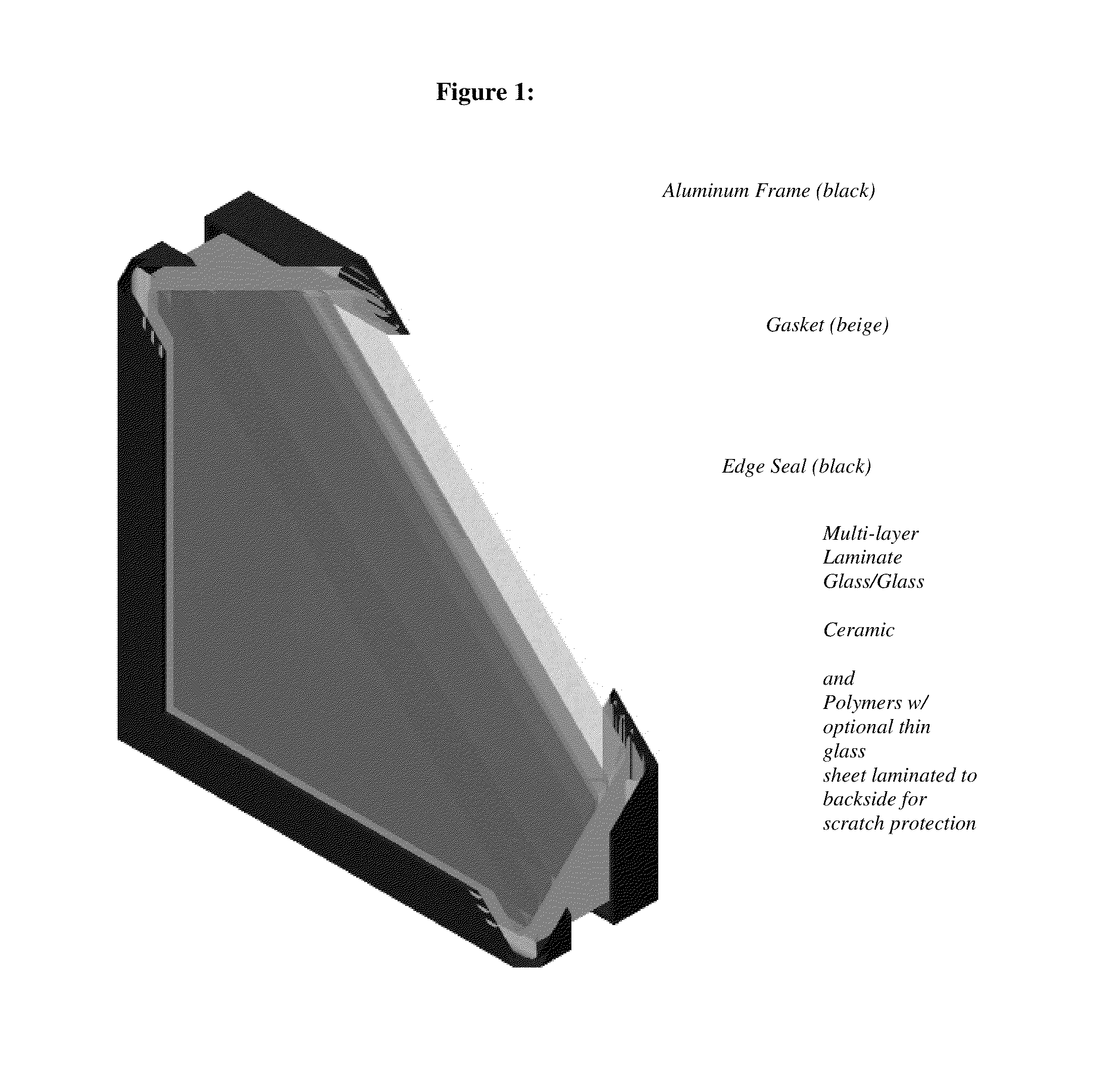
[0012]All laminate layers are joined together with polymer interlayers. Each interlayer may range from about 10 to 80 mil thick in the finished laminate. Most preferably the polymer interlayer is polyurethane or polyvinylbutyral. Select interlayers may be reinforced, for example by incorporating a tear-resistant PET film. Optionally, a thin glass layer may be laminated to the backside of the spall layer to protect the polymer surface against degradation including scratches and chemical attack by window cleaning agents.

Problems solved by technology

Systems employing transparent ceramic materials such as, for example, transparent spinel, sapphire, or AlON, show superior ballistic performance over traditional glass-based systems, but are often not available in larger sizes and volumes.
Currently, the cost per square inch for these systems is typically more than 5 times higher than for glass-based systems offering comparable protection.

Method used


Image

  • Lightweight transparent armor window
  • Lightweight transparent armor window
  • Lightweight transparent armor window

Examples


example 1

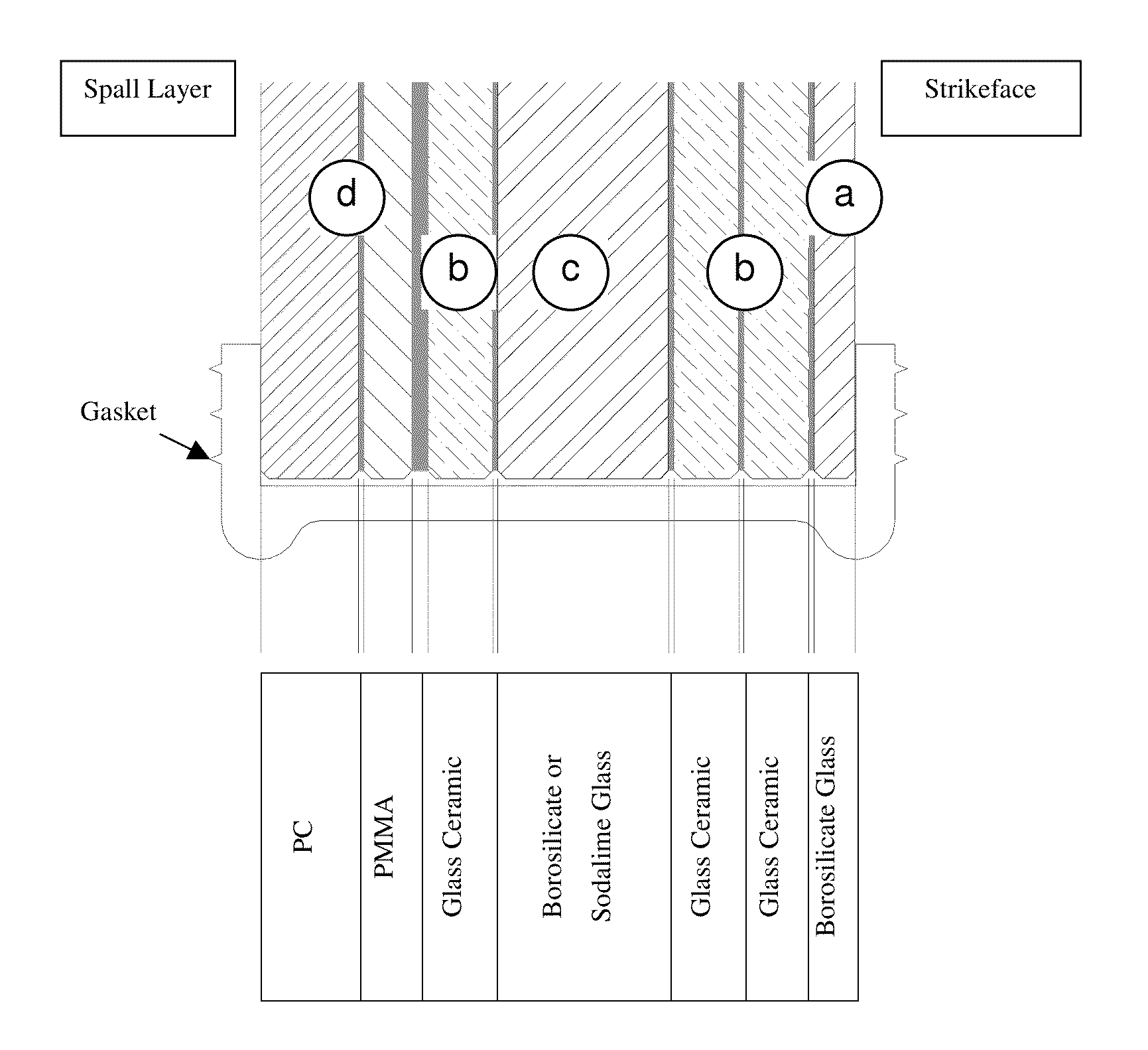
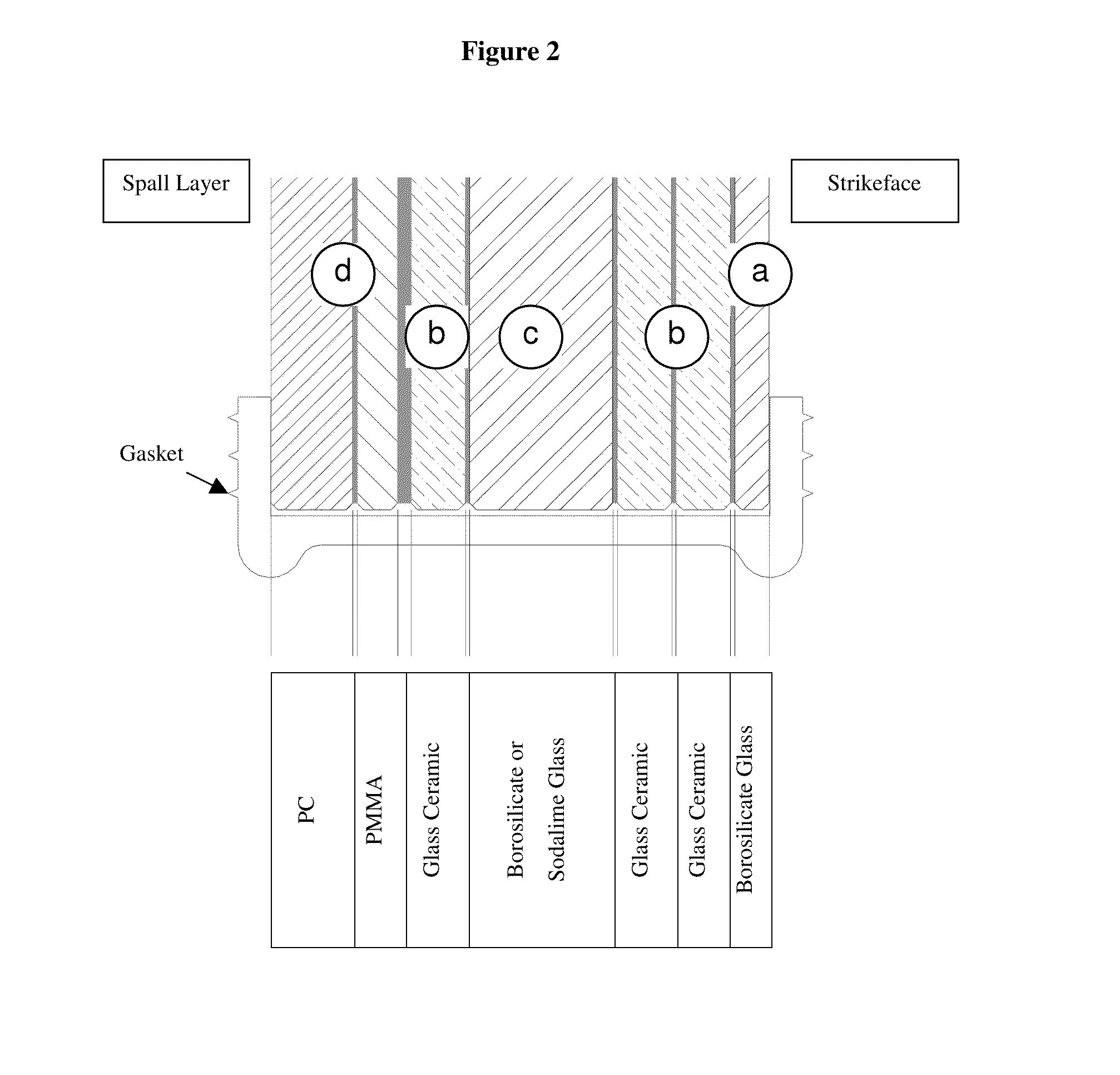
[0082]The following arrangement of laminate layers provides protection against 0.30 cal. AP-M2 projectiles at speeds of up to 2750 fps. The window, without frame, exhibits an areal density of 30 psf or less.[0083]Strike face: SCHOTT BOROFLOAT with a thickness between 4 mm to 6 mm[0084]1st Interlayer: 25 mil PU (Polyurethane) film (Huntsman PE501 or similar)[0085]1st Layer (b): SCHOTT ROBAX Glass Ceramic with a thickness between 7 mm to 8 mm[0086]2nd Interlayer: 25 mil PU film (Huntsman PE501 or similar), or 25 mil PVB (Polyvinylbutyral) film[0087]2nd Layer (b): SCHOTT ROBAX Glass Ceramic with a thickness between 7 mm to 8 mm[0088]3rd Interlayer: 25 mil PU film (Huntsman PE501 or similar), or 25 mil PVB film (Polyvinylbutyral)[0089]3rd Layer (c):[0090]Option A: single-layer SCHOTT BOROFLOAT with a thickness between 18 mm to 21 mm[0091]or[0092]Option B: double-layer SCHOTT BOROFLOAT with a thickness of each individual layer between[0093]9 mm to 11 mm, bonded with 25 mil PVB or PU film...

example 2

Ballistic Test Results

[0101]Small, multi-layer test coupons (100 mm×100 mm) are mounted on a 12″×12″×12 mm thick polycarbonate backing. The samples are tested in a configuration similar to the one shown in FIG. 9. The test projectile is 0.30 cal. AP-M2 at the indicated nominal speed (2250 fps or 2750 fps). Based on the test results, the design described in Example 1 is derived combining the two multi-layer sequences marked with an asterisk in Table 2 to accommodate for scaling.

TABLE 1ABallistic Test Results - 2250 fps impacts by 0.30 cal. AP-M2ShotWeights (Grains)Velocity Data (ft / sec)PenetrationNumberProjectilePropellantNo. 1No. 2AverageDescription / Pen. into PB9-17564162.834.4228322812282No Penetration9-17565163.434.4225922592259No Penetration9-17566163.134.4225422542254No Penetration9-17567163.534.4222222222222No Penetration9-17568163.334.4228422842284No Penetration9-17569163.434.4225722572257No Penetration9-17570163.634.4228122802281No Penetration9-17571163.434.4226822672268No Pe...

example 3

Multi-Hit Example

[0103]Three 500 mm×500 mm test coupons for multi-hit testing are prepared, and tested against an 0.30 cal. AP-M2 round at nominal 2750 fps; the shot pattern is a 120 mm triangle, the shot sequence is 12 O'clock, 4 O'clock and 8 O'clock. The nominal areal density of the samples is 29 psf; due to slight variations in the thickness of the individual glass and glass-ceramic layers, the areal density of the samples as manufactured is 29.7 psf (samples 1 and 2) and 30 psf (sample 3).

The samples have the following structure:

500 mm × 500 mm, edges sealed, framelessSample 1Strikeface6 mm BorofloatInterlayerHuntsman PE-501 - 25 milPly 018 mm Robax Glass-ceramicInterlayerHuntsman PE-501 - 25 milPly 028 mm Robax Glass-CeramicInterlayerHuntsman PE-501 - 25 milPly 0321 mm BorofloatInterlayerHuntsman PE-501 - 25 milPly 048 mm RobaxInterlayerHuntsman PE-501 - 75 milSpall-Layer9 mm PMMA laminated to9 mm PC (Lexan)Sample 2Strikeface6 mm BorofloatInterlayerHuntsman PE-501 - 25 milPly ...


PUM

PropertyMeasurementUnit
thicknessaaaaaaaaaa
thickaaaaaaaaaa
thickaaaaaaaaaa

Abstract

The invention relates to a lightweight transparent armor laminate comprising layers of borosilicate glass, layers of transparent glass-ceramics and a polymer spall layer of polycarbonate and / or polymethyl methacrylate. The layers are bound by polyurethane and / or polyvinylbutyral interlayer films.

Description

[0001]This application claims the benefit of the filing date of U.S. Provisional Application Ser. No. 60 / 975,661 filed Sep. 27, 2007.[0002]Commercially available, glass-based transparent armor typically consists of multiple glass and polymer layers, which are laminated together to form a relatively thick composite. The resulting composite must be transparent and essentially free of optical distortion while providing maximum protection against ballistic impact of projectiles and fragments at minimum weight and minimum cost. Of particular interest are transparent laminates, which restrict the destruction caused by the projectile locally to ensure maximum residual vision and provide protection against multiple hits.[0003]To successfully stop a projectile, impact resistant transparent laminates typically engage various defeat mechanisms, including projectile fragmentation and mass removal by projectile erosion. Systems employing transparent ceramic materials such as, for example, transp...

Claims


Application Information

Patent Timeline
Patent Type & Authority Applications(United States)
IPC IPC(8): F41H5/04
CPCF41H5/0407B32B17/10045B32B17/10761B32B17/1077B32B2333/12B32B2369/00B32B17/10119Y10T428/24942Y10T428/31518Y10T428/31601Y10T428/31507
Inventor WEINHOLD, CARSTEN
Owner ORAN SAFETY GLASS INC
Why Eureka
Try Eureka