
Resin-attached lead frame, method for manufacturing the same, and lead frame

a lead frame and resin-attached technology, applied in the direction of electrical equipment, semiconductor devices, semiconductor/solid-state device details, etc., can solve the problems of brownish discoloration, light extraction efficiency decreasing over time, etc., to prevent the lead frame from degrading with time, and enhance the extraction efficiency of light. , the effect of efficient reflection

Active Publication Date: 2013-11-21
DAI NIPPON PRINTING CO LTD
View PDF19 Cites 36 Cited by
  • Summary
  • Abstract
  • Description
  • Claims
  • Application Information

AI Technical Summary

Benefits of technology

The invention provides a way to improve the efficiency of LED devices by using a layer of vapor-deposited or sputtered aluminum on the lead frame. This helps to reflect light from the LED elements and prevents degradation of the lead frame over time.

Problems solved by technology

Depending upon the type of synthetic resin constituting the reflecting plate, however, the ultraviolet rays emitted from the LED elements may cause yellowish discoloration due to deterioration, thus resulting in light extraction efficiency decreasing over time.
Additionally, the silver plating of the lead frame causes a reaction with the hydrogen sulfide contained in air, and leads to brownish discoloration,

Method used


Image

  • Resin-attached lead frame, method for manufacturing the same, and lead frame
  • Resin-attached lead frame, method for manufacturing the same, and lead frame
  • Resin-attached lead frame, method for manufacturing the same, and lead frame

Examples


first embodiment

[0042]Hereunder, a first embodiment of the present invention will be described referring to FIGS. 1 to 10.

[0043]Lead Frame Configuration

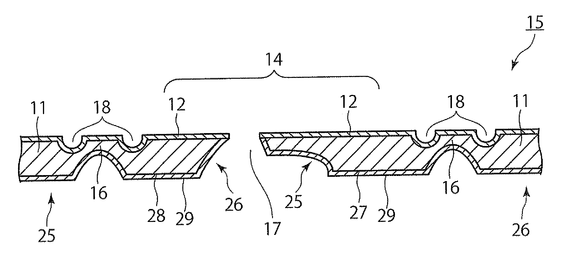
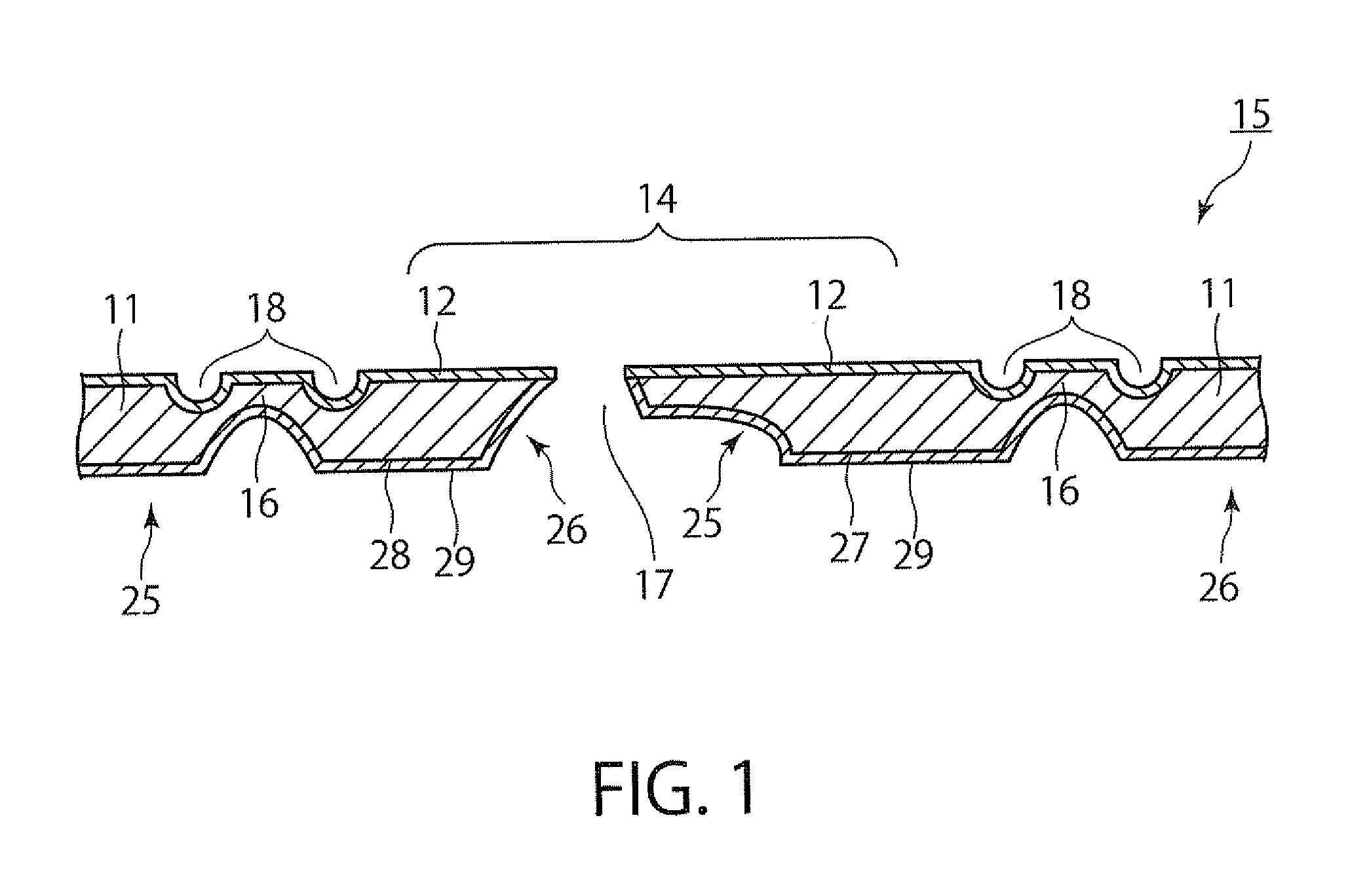
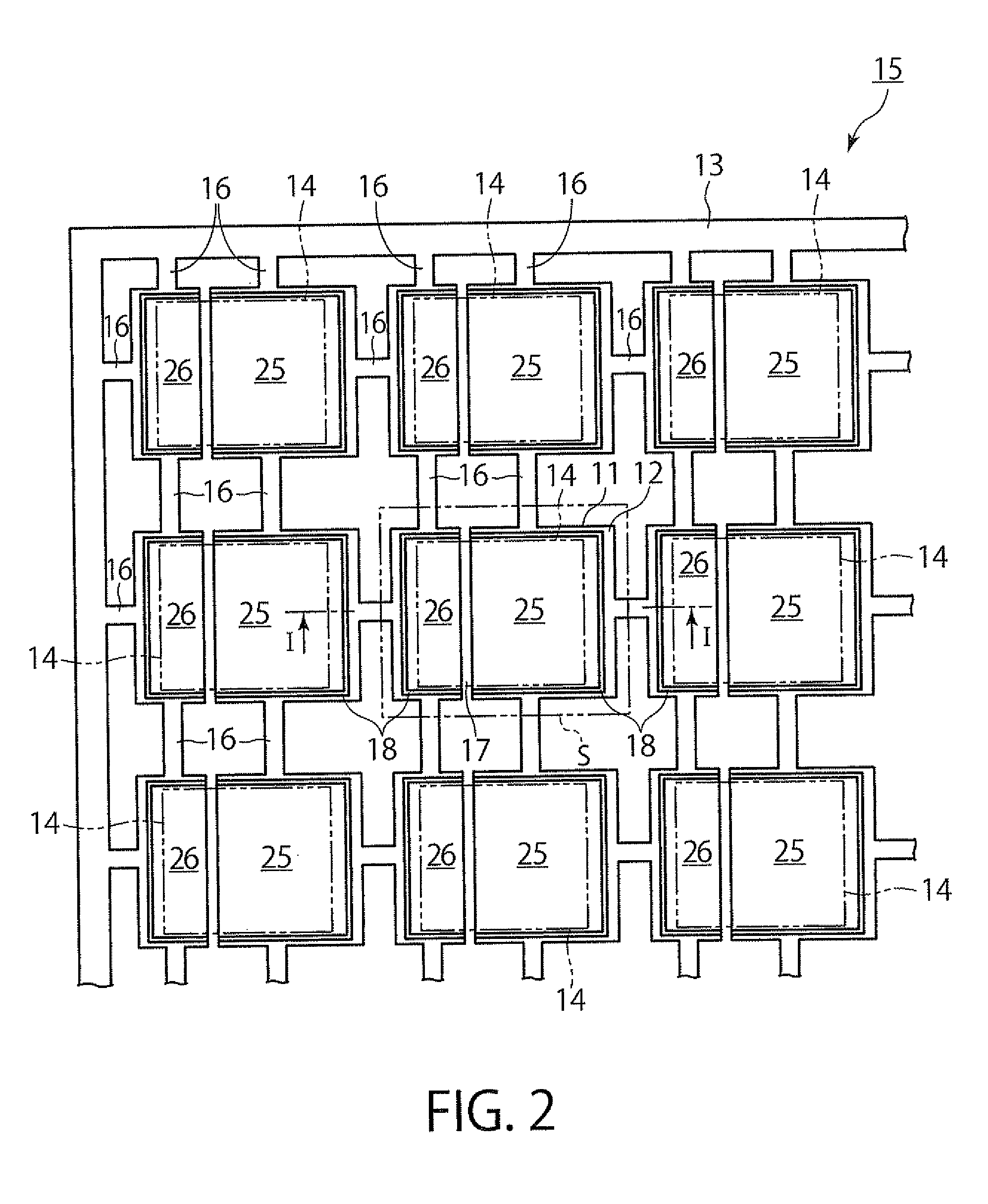
[0044]First, a lead frame for resting LED elements, according to the present embodiment is outlined below per FIGS. 1 and 2. FIGS. 1 and 2 are a cross-sectional view, and a plan view, respectively, of the lead frame according to the present embodiment.

[0045]The lead frame 15 shown in FIGS. 1 and 2 includes a lead frame main body 11 having a plurality of LED element resting regions 14, and metallic layers 12 provided on upper surfaces of the LED element resting regions 14 of the lead frame main body 11, the metallic layers 12 each functioning as a reflecting layer for reflecting light emitted from an LED element 21.

[0046]The lead frame main body (hereinafter referred to simply as the lead frame body) 11 is formed from a sheet of metal. The metal sheet constituting the lead frame body 11 can be of a material such as copper, copper alloy, or 42-alloy (...

second embodiment

[0115]Next, a second embodiment of the present invention is described below referring to FIGS. 11 to 16. FIGS. 11 to 16 show the second embodiment of the present invention. The second embodiment shown in FIGS. 11 to 16 differs from the first embodiment in that a vapor-deposited aluminum layer or sputtered aluminum layer 12 is also provided on inner walls 23b of a reflecting resin section 23, and all other elements are substantially the same as those in the first embodiment. In FIGS. 11 to 16, the same elements as those of the embodiment shown in FIGS. 1 to 10 are each assigned the same reference number or symbol, and detailed description of these elements is omitted herein.

[0116]Resin-Attached Lead Frame Configuration

[0117]First, a resin-attached lead frame according to the present embodiment is outlined below per FIGS. 11 and 12. FIGS. 11 and 12 are a cross-sectional view, and a plan view, respectively, of the resin-attached lead frame according to the present embodiment.

[0118]As s...


PUM


Abstract

A resin-attached lead frame includes a lead frame main body having a plurality of die pads (LED element resting portions) and a plurality of lead portions spaced from the die pads, the lead frame main body further including LED element resting regions each formed over an area including an upper surface of each of the die pads and an upper surface of each of the lead portions. A reflecting resin section surrounds each LED element resting region of the lead frame main body. A vapor-deposited aluminum layer or a sputtered aluminum layer is provided on respective upper surfaces of the LED element resting regions of the lead frame main body.

Description

TECHNICAL FIELD[0001]The present invention relates to a resin-attached lead frame used for resting LED elements thereupon, to a method for manufacturing the lead frame, and to a lead frame.BACKGROUND ART[0002]In recent years, optical devices, especially LED devices, are expanding their applications as illumination for cellular phones, or as backlights for liquid crystals. These applications are expanding to the general lighting or illumination recently replacing incandescent light bulbs. In general, however, the light-emission efficiency of LED devices in one wafer has a tendency to vary significantly. In addition, these LED devices are still too low in light-emission efficiency to find their use in general lighting / illumination applications, and thus a plurality of LED elements need to be mounted in one LED device.[0003]Among the packaging techniques for these LED devices are one in which LED elements are mounted on an organic substrate of a glass epoxy or the like and after wire b...

Claims


Application Information

Patent Timeline
Patent Type & Authority Applications(United States)
IPC IPC(8): H01L33/62H01L33/56
CPCH01L33/62H01L33/56H01L33/486H01L33/60H01L2224/48091H01L2224/48247H01L23/49861H01L2924/00014H01L2933/0033H01L33/46
Inventor IKENAGA, CHIKAOODA, KAZUNORI
Owner DAI NIPPON PRINTING CO LTD
Features
  • Generate Ideas
  • Intellectual Property
  • Life Sciences
  • Materials
  • Tech Scout
  • Unparalleled Data Quality
  • Higher Quality Content
  • 60% Fewer Hallucinations
Learn More