Tube coupling joint

Active Publication Date: 2013-11-21
FUROUERU
View PDF15 Cites 17 Cited by
  • Summary
  • Abstract
  • Description
  • Claims
  • Application Information

AI Technical Summary

Benefits of technology

[0039]According to the tube coupling joint set forth in the above item [3], the hole peripheral edge of the insertion hole in the cap nut is jutted out in a mountain-shaped sectional geometry toward the central axis and the inlet of the threaded hole, and the bent portion of the tube is sandwiched between the hole peripheral edge of the insertion hole and the distal end portion of the inner cylindrical portion of the joint main body. Thereby, the tensile strength of the tube with respect to the joint main body is further increased, whereby the tube can be more positively prevented from accidentally coming off.
[0040]According to the tube coupling joint set forth in the above item [4], the inside diameter of the outer cylindrical portion of the joint main body is set at a value smaller than the largest outside diameter of the one end portion of the tube flared by the greatest wall thickness portion of the ring. And, with the cap nut to the joint main body being tightened, the flared one end portion of the tube is press-fitted to the innermost recess portion of the recessed groove of the cap nut, thereby, the seal performance can be further stabilized to enhance the airtightness.
[0041]According to the tube coupling joint set forth in the above item [5], on the inner periphery side of the distal end portion of the inner cylindrical portion of the joint main body, there are provided a first inner tapered portion which is formed by chamfering the inner cylindrical portion by a thickness equal to an amount by which the distal end portion would be deformed toward the central axis with the cap nut being tightened to the joint main body, and a second inner tapered portion inclined, on the distal end side of the first inner tapered portion, at an angle equal to or larger than the inclination angle thereof for preventing residence of a fluid as a medium to be transported. The tapered geometry of the first inner tapered portion is not limited to a single-tapered one, and may be a multiple-tapered geometry, such as a double- or triple-tapered

Problems solved by technology

However, with the aforementioned conventional general inner ring type (FIG. 19 to be referenced), there have been problems that both ends of the ring inserted into the tube tend to cause penetration of the fluid, and residence of the fluid.
Further, another problem has been presented that the ring is deformed to an inside diameter smaller than that of the tube, thereby causing a pressure drop in transportation of the fluid.
Still further, another problem has been presented that, even if the ring has not been inserted into the tube, the tube can be incorporated into the joint main body, as shown in FIG. 21, and whether or not the ring has been inserted into the tube cannot be known from the outside, therefore, in the event that the ring has not been inserted into the tube, the tube may be drawn with no resistance to the d

Method used


Image

  • Tube coupling joint
  • Tube coupling joint
  • Tube coupling joint

Examples


Example

[0070]FIG. 1 to FIG. 16 illustrate a first embodiment of the present invention.

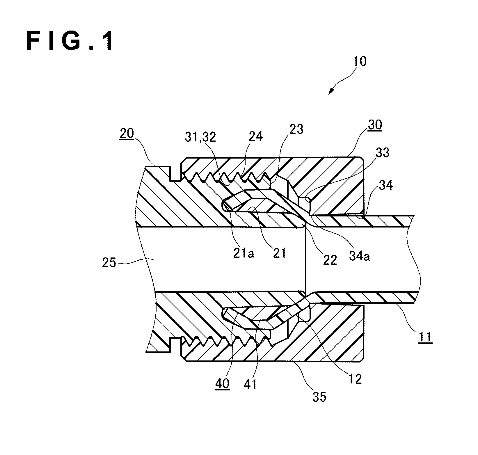
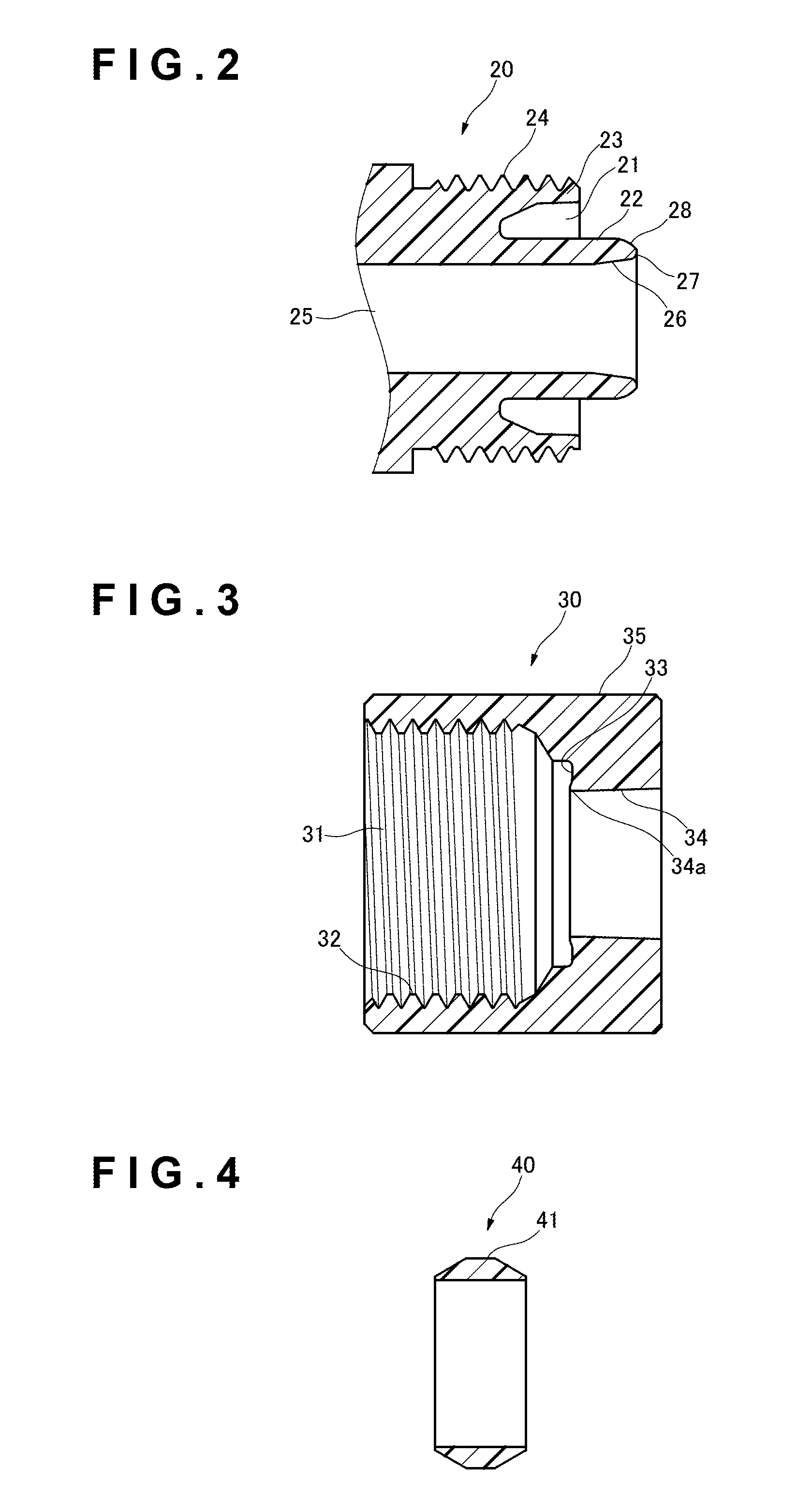
[0071]FIG. 1 is a critical portion sectional view showing a tube coupling joint 10 according to the present embodiment; FIG. 2 is a sectional view of one end portion of a joint main body 20 of the tube coupling joint 10; FIG. 3 is a sectional view of a cap nut 30 in the tube coupling joint 10; FIG. 4 is a sectional view of a ring 40 in the tube coupling joint 10 and FIG. 5 is a perspective view showing the appearance of the tube coupling joint 10.

[0072]As shown in FIG. 1 to FIG. 5, the tube coupling joint 10 is constituted by a combination of a tube 11, the joint main body 20, the cap nut 30 and the ring 40. With such tube coupling joint 10, the ring 40 is press-fitted to one end portion 12 of the tube 11 for flaring it and holding it in the flared state; the flared one end portion 12 of the tube 11 is coupled to the joint main body 20; and with the tube 11 having been passed through the cap nut 30, the c...

Example

[0123]FIG. 17 and FIG. 18 show a second embodiment of the present invention.

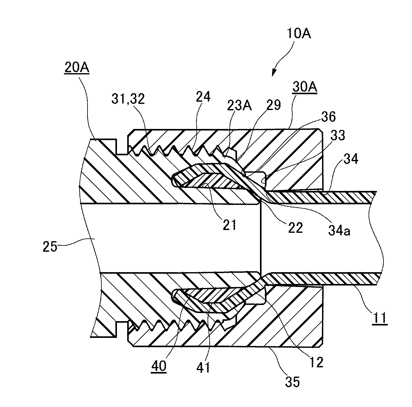
[0124]A tube coupling joint 10A of the present embodiment is similar, in basic configuration, to the tube coupling joint 10 according to the first embodiment as described above, except that an outer cylindrical portion 23A of a joint main body 20A is different in specific configuration. FIG. 17 is a critical portion sectional view illustrating the tube coupling joint 10A according to the present embodiment, and FIG. 18 is a critical portion sectional view illustrating the tube coupling joint 10A while being assembled. A cap nut 30A in FIG. 18 is shown as a sectional end view.

[0125]With the tube coupling joint 10A according to the present embodiment, the outer cylindrical portion 23A of the joint main body 20A is formed such that, when the inner cylindrical portion 22 of the joint main body 20A has been inserted into the ring 40 while the flared one end portion 12 of the tube 11 has been press-fitted to the i...


PUM

PropertyMeasurementUnit
Currentaaaaaaaaaa
Currentaaaaaaaaaa
Currentaaaaaaaaaa

Abstract

By previously press-fitting a ring (40) into one end portion (12) of a tube (11), the one end portion (12) is held in the flared state. With an inner cylindrical portion (22) of the joint main body (20) having been inserted into this ring (40) while the one end portion (12) having been press-fitted into a recessed groove (21) to the innermost recess portion, a greatest wall thickness portion (41) of the ring is covered. In this state, with a cap nut (30) being screwed with the joint main body (20), the greatest wall thickness portion (41) of the ring is pressed against the inner cylindrical portion (22) together with the one end portion (12) through an outer cylindrical portion (23), and a hole peripheral edge (34a) of an insertion hole (34) of the cap nut is pressure-contacted with a bent portion (12c) of the tube by the ring (40).

Description

TECHNICAL FIELD[0001]The present invention is related to a tube coupling joint for use as means for coupling tubes to one another that provide flow paths for any fluids including ultrapure water, which is handled in various processes, such as those for semiconductor manufacturing, liquid crystal manufacturing, medical supply / pharmaceutical manufacturing, food processing, and the like, and fluids dangerous to human bodies, such as sulfuric acid and hydrochloric acid.BACKGROUND ART[0002]Conventionally, as this type of tube coupling joints, those made of a resin, which is typified by a fluorocarbon resin, are well known, and they are divided into two broad general categories; i.e., the “inner ring type” as shown in FIG. 19, which inserts a ring into the inside of the tube, and the “flare type” as shown in FIG. 20, which flares the tube.[0003]As the tube coupling joint of inner ring type, that as disclosed in Patent Document 1 is known, and as the tube coupling joint of flare type, that...

Claims


Application Information

Patent Timeline
IPC IPC(8): F16L19/04
CPCF16L19/04F16L19/0283F16L33/226F16L47/041F16L33/22
Inventor SEKINO, YOHEI
Owner FUROUERU
Why Eureka
Try Eureka