Integrated start-up bias boost for dynamic error vector magnitude enhancement

a technology of dynamic error vector and boost, which is applied in the direction of high-frequency amplifiers, gated amplifiers, gain control, etc., can solve the problems of inability to physically present such a large capacitor, inability to train or characterize, and inability to accurately process the signal by the receiving circui

Active Publication Date: 2013-11-21
MICROSEMI
View PDF1 Cites 20 Cited by
  • Summary
  • Abstract
  • Description
  • Claims
  • Application Information

AI Technical Summary

Benefits of technology

[0008]An example circuit that corrects for start-up transients in power amplifiers includes a boost generator, a reference element, a bias element, and a power amplifier. The boost generator can include a delay element, a transconductance element, or both. The delay element is arranged to produce a delay waveform signal that is responsive to an input voltage signal. The transconductance element has an input that receives the delay waveform signal from the delay element and is arranged to provide an output boost current that is based on the delay waveform signal and a gain of the transconductance element. The reference element provides an output bias current that is responsive to a static reference current and the boost c

Problems solved by technology

Upon powering on, the power amplifier experiences a period of time during which the signal that is transmitted is changing and the transmission characteristics of the power amplifier are also changing, which is difficult to train or characterize by other circuit components or other circuits coupled to the power amplifier circuit.
This assumption of no further changes to the manner in which the signal is changing lea

Method used


Image

  • Integrated start-up bias boost for dynamic error vector magnitude enhancement
  • Integrated start-up bias boost for dynamic error vector magnitude enhancement
  • Integrated start-up bias boost for dynamic error vector magnitude enhancement

Examples


Embodiment Construction

[0023]In the drawings, which are not necessarily to scale, like or corresponding elements of the disclosed systems and methods are denoted by the same reference numerals.

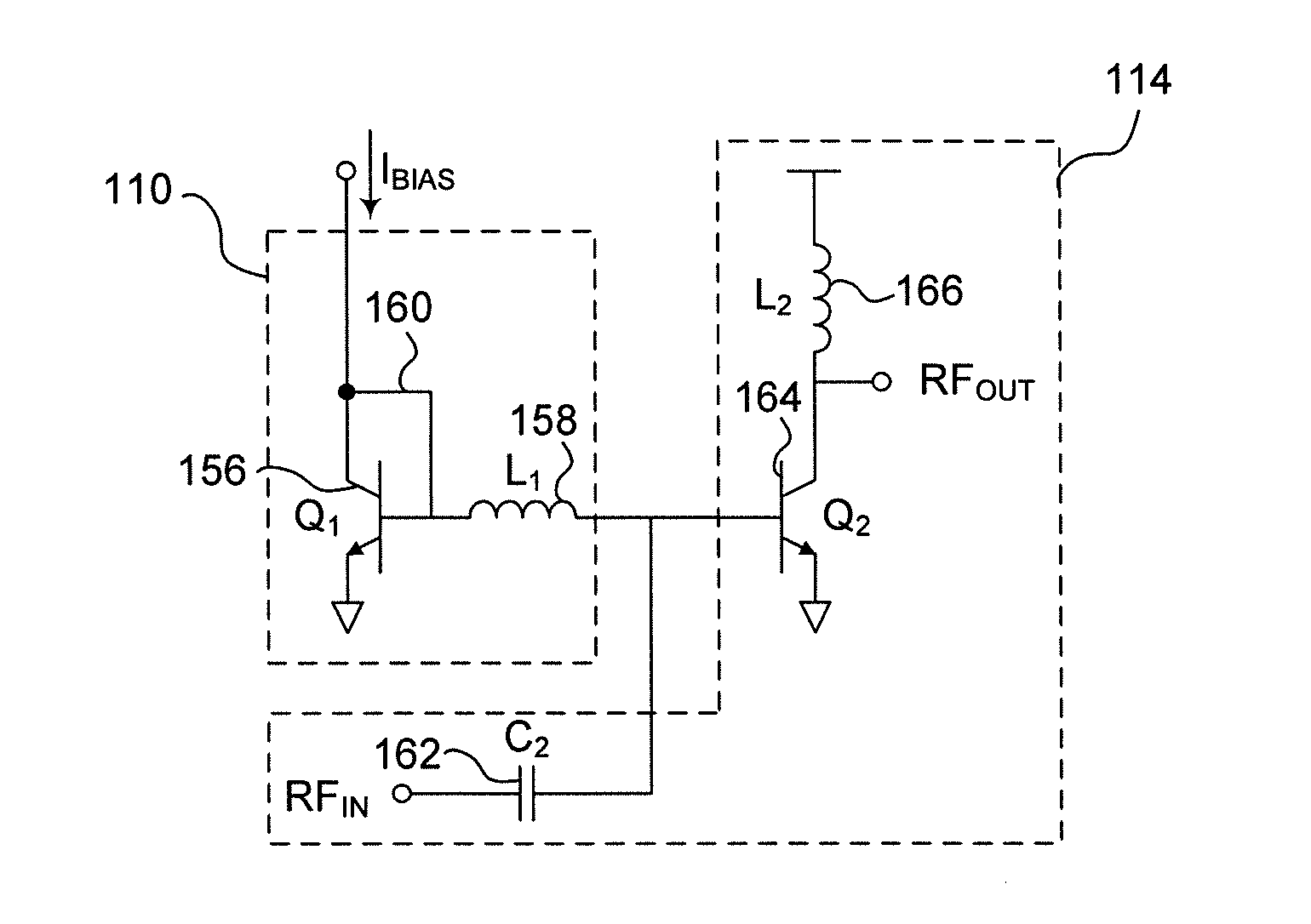
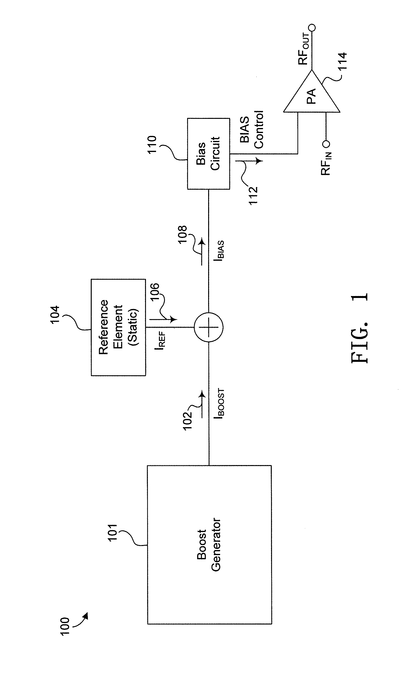
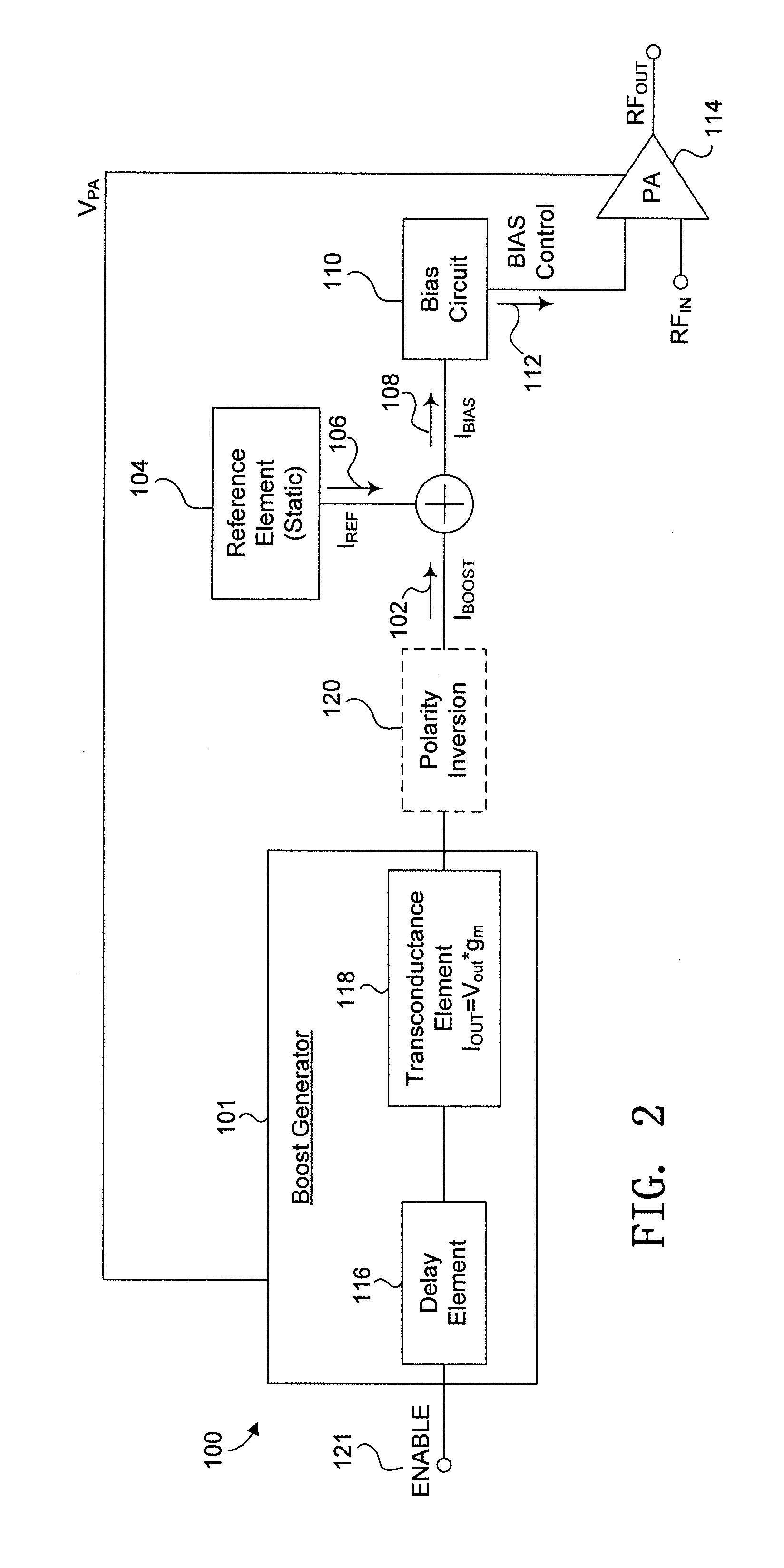
[0024]To correct for start-up transients inherent in power amplifiers, such as the LX5585 and LX5590 power amplifiers manufactured by Microsemi Corporation®, the disclosed circuits and methods provide for separating the circuit elements used to set the delay from those circuit elements used to set the output magnitude of the bias current and the characteristics of the output signal of the power amplifier. By separating the delay and the output magnitude of the bias current, the output signal of the power amplifier compensates for the start-up transients inherent in power amplifiers, in many environments, specifically in a monolithic solution for example. This arrangement can provide adjustable control mechanisms and the ability to control the circuit's behavior in any standard CMOS / BiCMOS process.

[0025]Referring now...


PUM


Abstract

Devices and methods for correcting for start-up transients in integrated power amplifiers are disclosed. A delay element is arranged to produce a delay waveform signal that is responsive to an input voltage signal. A transconductance element has an input that receives the delay waveform signal and is arranged to provide an output boost current that is based on the delay waveform signal and a gain of the transconductance element. A reference element provides an output bias current that is responsive to a static reference current and the boost current. A bias element has an input that receives the bias current and is arranged to provide a bias control output. A power amplifier is responsive to the bias control output and is arranged to provide an amplified power output. In some examples, the boost current is adjusted based on a supply voltage and an input power of the power amplifier.

Description

CROSS REFERENCE TO RELATED APPLICATIONS[0001]This application claims the benefit of copending U.S. provisional patent application Ser. No. 61 / 648,504, filed May 17, 2012.FIELD OF THE INVENTION[0002]This disclosure relates to enhancing power amplifier performance and more particularly to enhancing power-on performance of a power amplifier in an integrated circuit.BACKGROUND OF THE INVENTION[0003]Power amplifiers may be integrated onto the same die as receiving or other types of amplifiers in many communications standards, such as wireless LAN. A switch permits transmission of signals through the antenna to / from either the power amplifier circuit or the receiving or other amplifier, depending on the needs of the communications circuit. When the power amplifier is transmitting signals, power is supplied to the power amplifier. When the power amplifier is not actively transmitting signals, power is not supplied to the power amplifier. Upon powering on, the power amplifier experiences a ...

Claims


Application Information

Patent Timeline
IPC IPC(8): H03G3/00
CPCH03G3/004H03F1/0261H03F1/0266H03F1/305H03F3/19H03F2200/18H03F2200/321H03F2200/504H03F2200/507H03G3/3042H03G3/3047H03F3/21H03G1/0088H03F3/45475H03F3/72H03F1/0277
Inventor HERSHBERGER, KYLEEPLETT, BRIANSANTINI, MARK
Owner MICROSEMI
Why Eureka
Try Eureka