Laminar Flow Jets

a jet and flow technology, applied in the field of laminar flow jets, can solve the problems of unsuitable glass working flames, more complicated tubing, conduits, chamber structures of burners, etc., and achieve the effects of reducing unburned gases, efficient flames, and high quality

Active Publication Date: 2013-11-21
HORN WALLACE +1
View PDF12 Cites 9 Cited by
  • Summary
  • Abstract
  • Description
  • Claims
  • Application Information

AI Technical Summary

Benefits of technology

[0007]Burners obtain these chemistries not only through appropriate jet shape, but also through exact alignment and axial concentricity of the inner tubes, conduits, and chambers that supply the different gases. The orientation of the jet on the gas burner faceplate also affects flame characteristics. This requires a difficult manufacturing process but is essential in establishing a laminar gas flow that produces a high quality and efficient flame (i.e. greatly reducing unburned gases).

Problems solved by technology

The greater the number of different gases, the more intricate the tubing, conduit, and chamber structure within the burner.
Poor jet design and shape can lead to turbulent flow, inadequate mix of multiple gases, unstable flames, discoloration of glass, unwanted impurities (called “scumming”) and a number of other consequences that make flames unsuitable for glass working.
Production costs increase significantly as the number of jets in the faceplate array increases.
Alternative oxygen sources are becoming widely used in the form of onsite oxygen concentrators and generators due to the increasing cost of tanked oxygen.

Method used


Image

  • Laminar Flow Jets
  • Laminar Flow Jets
  • Laminar Flow Jets

Examples


embodiment 300

[0079]FIG. 18 shows an alternate embodiment 300 in which a series of tubes abut the bottom surface of faceplate 2, as opposed to extending through faceplate openings and terminating flush with the top surface of faceplate 2 as previously disclosed. This embodiment 300 may be employed alone as shown in FIG. 18, or in a series as depicted in FIG. 19. The faceplate 2 is broken into sections, each section having specifically shaped openings to allow the passage of gas from the tube, through the conduits of the faceplate, and up to the surface.

[0080]This particular embodiment depicts a faceplate 2 broken into three pieces 301, 302, and 303. These faceplate pieces act as inserts that are placed on top of the exposed tubes and conduits. First faceplate piece 301 is the outer donut shaped ring that conceals a portion of the outer tubes 320 such that only an opening 325, generally shaped as a half-moon, is exposed to the surface. In this embodiment, first faceplate piece 301 covers a portion...

second embodiment

[0089]Another embodiment of the invention is shown in FIG. 24 which provides a dual flow burner head 230 constructed from inter-fitting square tubes 233 positioned within an array of drilled holes 235 in the faceplate 232. This construction is more economical than the previous embodiment. As shown here in FIG. 24 and depicted in FIG. 26b, the diagonal dimension of the square tube is approximately equal to the inside diameter of the faceplate hole. This provides an interference fit, or nesting, of the square tubes 233 within the faceplate holes 235 and provides an accurate coaxial alignment of the two fluid conduits formed by this arrangement. Namely, a first conduit is defined by the space within the faceplate hole 235 but around the periphery of the square tube 233, and a second conduit is the square tube itself. FIG. 25 depicts the alignment and placement of the tubes and the fitting of the tubes 233 within the faceplate holes 235 after the holes have been drilled. This constructi...


PUM


Abstract

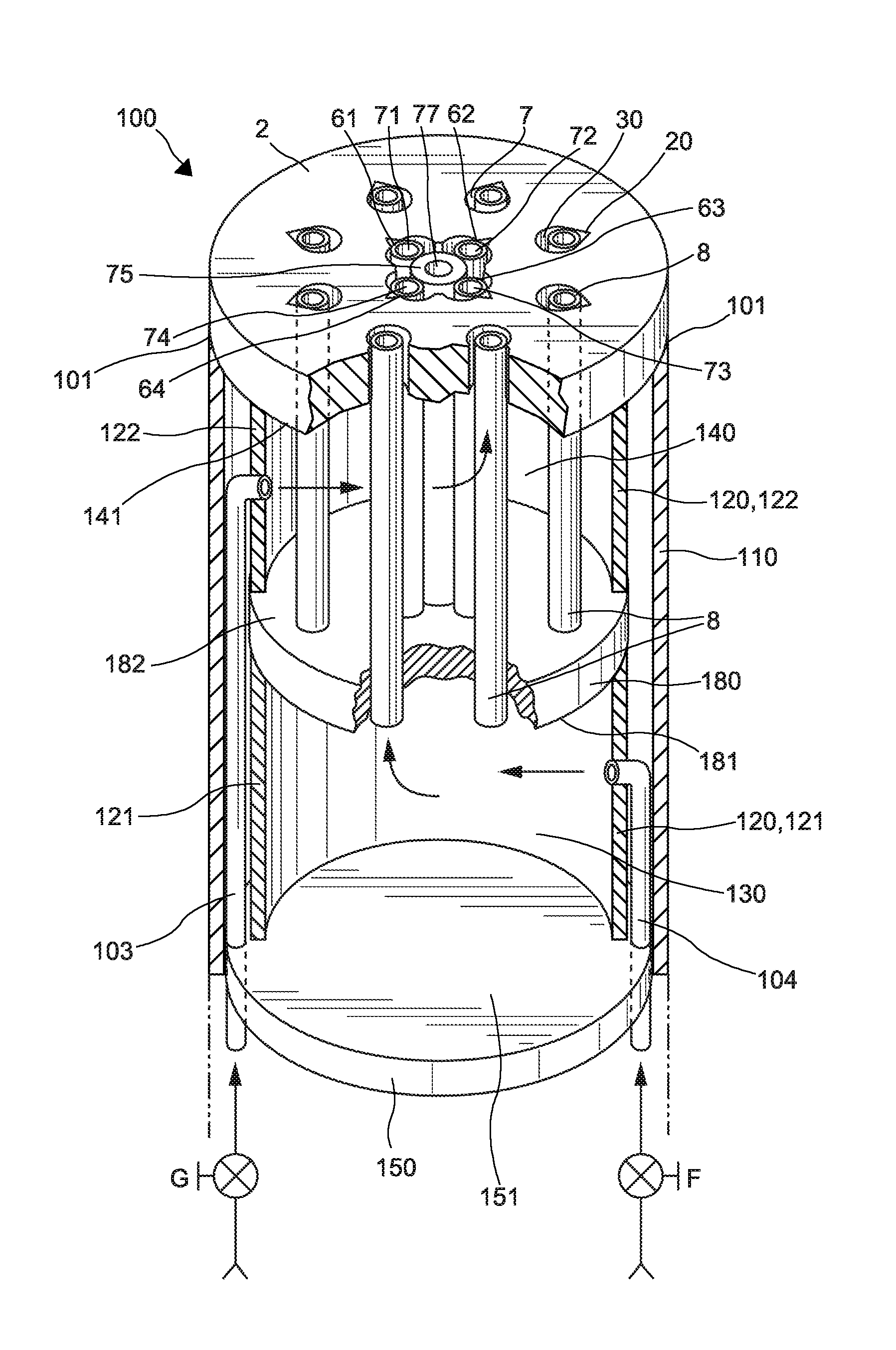
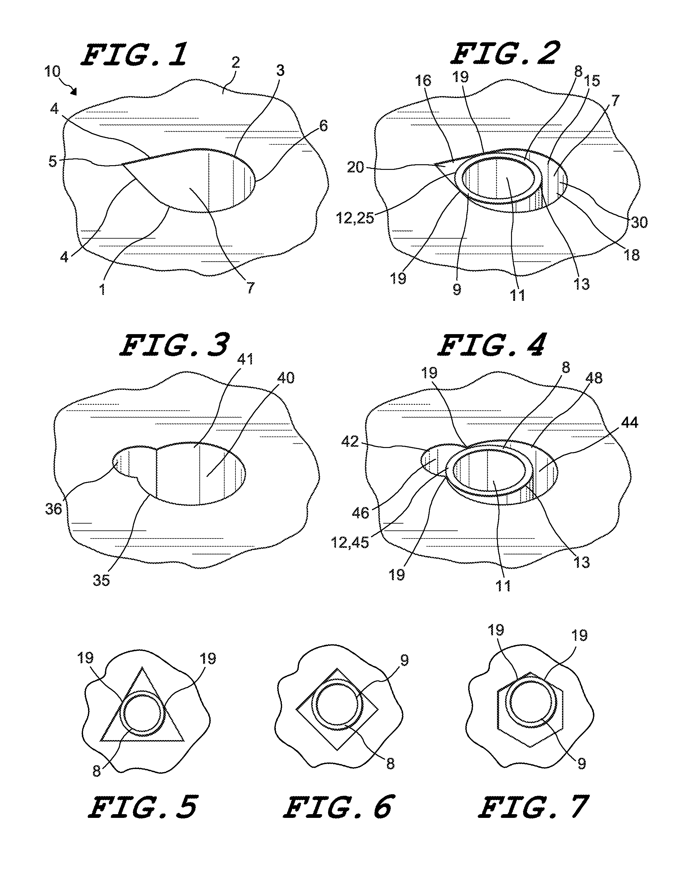
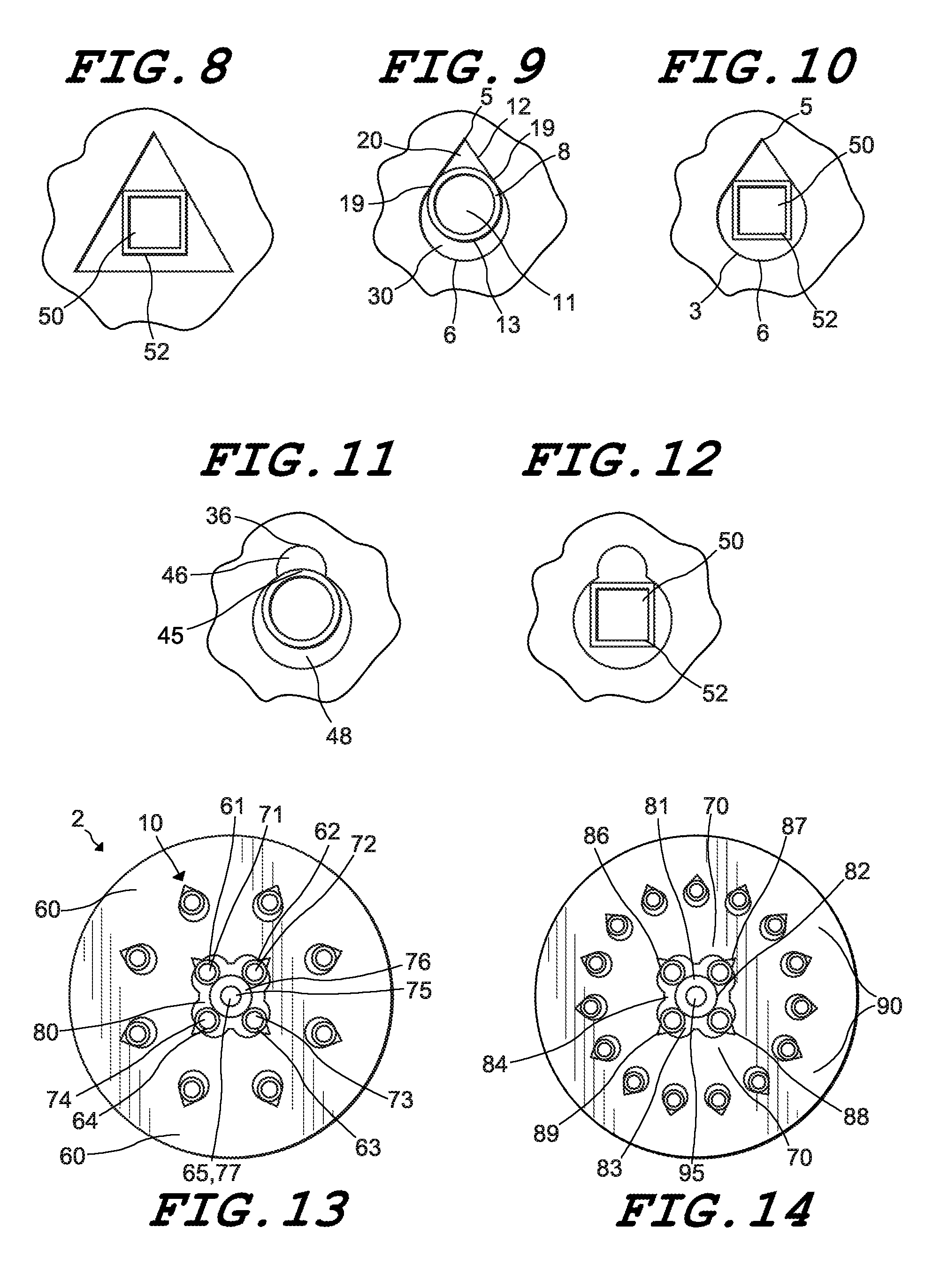
A laminar flow jet for a surface mix gas burner that provides increased stability, adjustability, and control over flame chemistries and characteristics. The present invention utilizes a novel shape, typically created by a tube having a cross-sectional shape and inserting it into a faceplate cutout, or conduit, having another cross-sectional shape. This nesting of one shape inside another promotes laminar gas flow and produces desired effects. Tubes may also be placed under the faceplate provided they maintain fluid communication with the conduits.
Further, a burner is constructed with adjacent gas delivery tubes of different cross-sectional shapes which are mechanically held in place radially. The tubes touch in a longitudinal direction at points along their respective inner and outer dimensions, achieving axial alignment and preserving the necessary laminar gas flow. This configuration greatly speeds manufacturing time which allows production of economical burners even when a greater number of jets is desired.

Description

RELATED APPLICATIONS[0001]This patent application is a continuation-in-part of co-pending patent application Ser. No. 13 / 209,538, entitled “Laminar Flow Jets” and filed Aug. 15, 2011, by the same inventors, priority of which is hereby claimed. That patent application is a continuation of patent application Ser. No. 12 / 410,934, also entitled “Laminar Flow Jets” filed Mar. 25, 2009, by the same inventors, since issued as U.S. Pat. No. 8,087,928, on Jan. 3, 2012. The contents of these aforementioned cross-referenced applications are hereby wholly incorporated by reference herein to the present application.FIELD OF THE INVENTION[0002]This invention relates to a laminar flow jet and its use in laminar fluid flow delivery system, particularly a gas burners (or “torch”) for use in the glass and quartz working industries and other industrial fields. More specifically, it relates to the shape and orientation of the jet, both singularly and in an array, on a gas burner and their capacity for ...

Claims


Application Information

Patent Timeline
Patent Type & Authority Applications(United States)
IPC IPC(8): F23C5/08F23D14/32F23D14/22
CPCF23C5/08F23D14/22F23D14/32F23D14/58F23D14/78F23D2214/00F23D2213/00Y02E20/34
Inventor HORN, WALLACEHORN, WILLIAM
Owner HORN WALLACE
Why Eureka
Try Eureka