Vehicle drive device

Inactive Publication Date: 2013-11-21
AISIN AW CO LTD +1
View PDF3 Cites 24 Cited by
  • Summary
  • Abstract
  • Description
  • Claims
  • Application Information

AI Technical Summary

Benefits of technology

[0025]According to the configuration, as in the case of the first engagement device, it is possible to improve the control accuracy of a hydraulic pressure applied to a side of the second piston opposite of the second engagement device opposite to a side on which a h

Problems solved by technology

However, the technology according to JP 2006-137406 A does not disclose supplying oil to friction members of the first engagement device.
Therefore, the technology according to JP 2006-137406 A does not address cooling the friction members of the first engagement device by supplying oil.
In the technology according to JP 2010-105450 A, however, during control of one of the first and second engagement devices, fluctuations in hydraulic pressure caused in a chamber for the one engagement device or operation of the hydraulic pressure supply system for the one engagement d

Method used


Image

  • Vehicle drive device
  • Vehicle drive device
  • Vehicle drive device

Examples


first embodiment

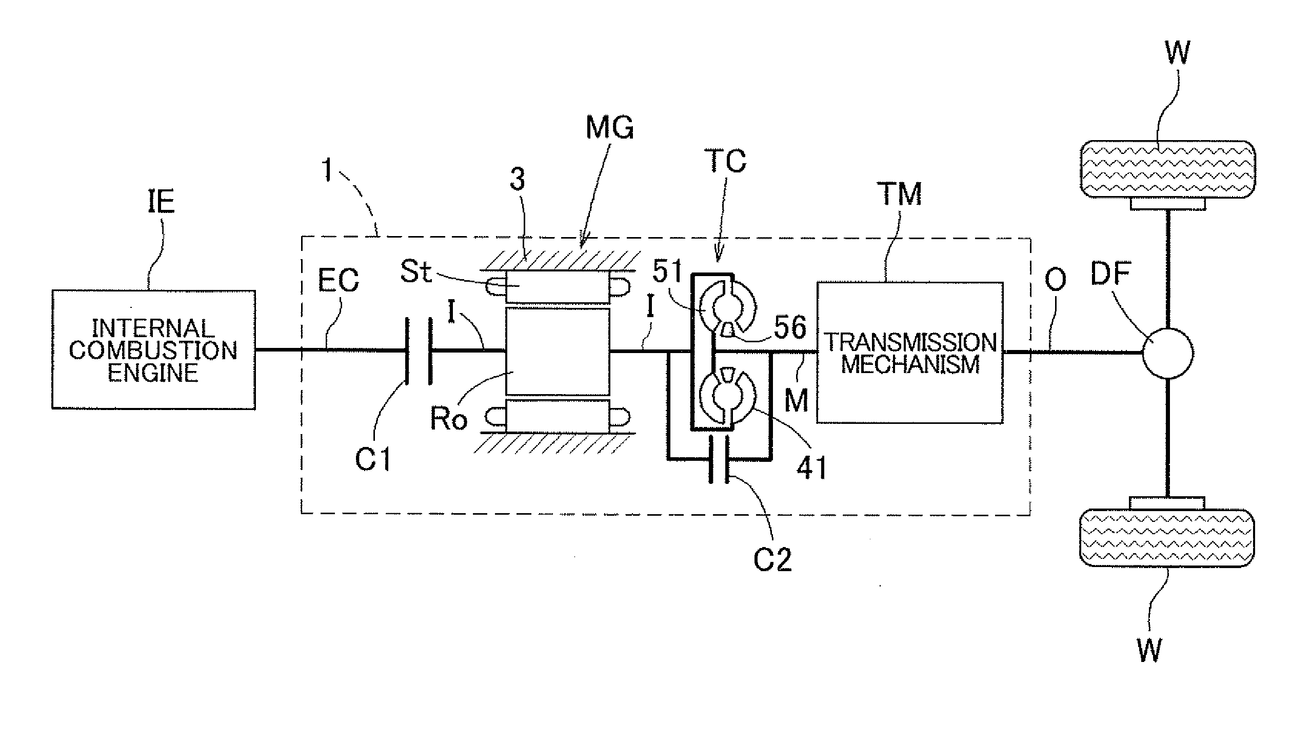
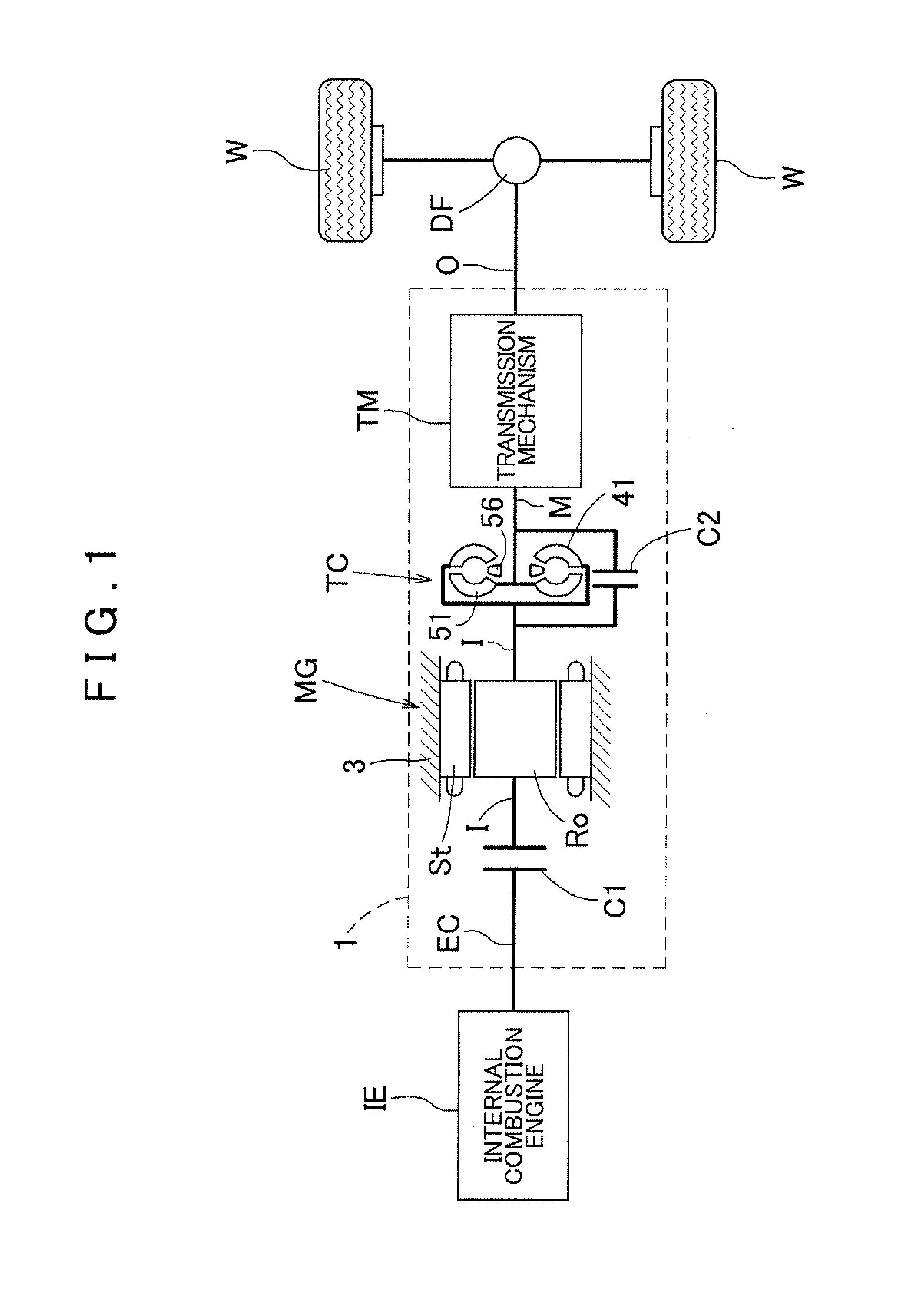
[0030]A vehicle drive device 1 (hereinafter referred to as “drive device 1”) according to an embodiment of the present invention will be described with reference to the drawings. FIG. 1 is a schematic diagram showing a schematic configuration of the drive device 1 according to the embodiment. As shown in the drawing, the drive device 1 according to the embodiment is generally configured to include an internal combustion engine IE and a rotary electric machine MG each serving as a drive force source, and to transfer drive forces of the drive force sources to wheels W via a power transfer mechanism. The drive device 1 includes an input shaft I drivably coupled to the rotary electric machine MG, an output shaft O drivably coupled to the wheels W, a first engagement device C1 that selectively drivably couples the input shaft I to the internal combustion engine IE, and a torque converter TC that serves as a fluid coupling provided on a power transfer path that connects between the input ...


PUM


Abstract

Mutual interference between a hydraulic pressure of a first engagement device and a hydraulic pressure of a second engagement device is suppressed even in the case where operation of the first engagement device and operation of the second engagement device coincide with each other. A vehicle drive device includes a first engagement device that selectively couples a rotary electric machine to an internal combustion engine, and a fluid coupling. The first engagement device includes a first oil chamber that is formed to apply a back pressure to a first piston. The fluid coupling includes a second oil chamber configured to control an engagement state of a second engagement device. The vehicle drive device includes a first control valve that controls a first oil chamber hydraulic pressure, and a second control valve that controls a second oil chamber hydraulic pressure independently of the first oil chamber hydraulic pressure.

Description

INCORPORATION BY REFERENCE[0001]The disclosure of Japanese Patent Application No. 2011-031995 filed on Feb. 17, 2011 including the specification, drawings and abstract is incorporated herein by reference in its entirety.BACKGROUND OF THE INVENTION[0002]The present invention relates to a vehicle drive device including an input member drivably coupled to a rotary electric machine, an output member drivably coupled to wheels, a first engagement device that selectively drivably couples the input member to an internal combustion engine, and a fluid coupling provided on a power transfer path that connects between the input member and the output member.DESCRIPTION OF THE RELATED ART[0003]Devices described in Japanese Patent Application Publication No. 2006-137406 (JP 2006-137406 A) and Japanese Patent Application Publication No.[0004]2010-105450 (JP 2010-105450 A) mentioned below are already known as examples of a vehicle drive device for a hybrid vehicle including an internal combustion e...

Claims


Application Information

Patent Timeline
IPC IPC(8): B60W20/00B60W10/02B60L50/16
CPCB60W20/40B60W10/023Y10S903/902F16D48/0206F16H61/143F16H2045/002F16H2045/021F16H2045/0226F16H2045/0284B60K6/48B60K2006/4825B60K6/40F16D48/02B60L2240/36B60L2240/423B60L2240/443B60L2240/445B60L2240/486B60L2270/145F16D25/0638F16D2048/0266F16D2048/0218F16D2500/10412F16D2500/70406F16D21/06B60L50/16Y02T10/62Y02T10/64Y02T10/7072Y02T10/70B60K6/38B60K6/547F16H45/00F16H45/02F16D25/10
Inventor KAMIYA, TOSHIHIKOMIYAZAKI, TERUFUMIIWASE, MIKIOYAMAGUCHI, TETSUYAYOSHIOKA, YUHEIKAWAMOTO, KEISUKE
Owner AISIN AW CO LTD
Why Eureka
Try Eureka