Device for skimming oil from the surface of water

a technology for skimming oil and water surface, which is applied in the field of skimming oil from the surface of water, can solve the problems of oil garbage disposal vessels not loss of recovered oil, and only being able to operate such equipment in calm conditions, so as to improve reliability and efficiency, and simplify the process

Inactive Publication Date: 2013-11-28
ZOTOV IGOR A +1
View PDF4 Cites 8 Cited by
  • Summary
  • Abstract
  • Description
  • Claims
  • Application Information

AI Technical Summary

Benefits of technology

[0014]A problem solved by the claimed invention is a possibility of the device operation on the high seas, improving reliability and efficiency with the simultaneous simplification of the process of the emulsified oil collection and treatment.

Problems solved by technology

A drawback of the known unit is the fact that the patented construction of the oil garbage disposal vessel does not allow to operationally carry out a collection of oil products because the oil-and-garbage room located in the bows cannot operate when heaving of the sea even at dead slow speed.
The operation of such equipment is only possible under calm conditions, i.e. in the protected waters.
When operated on a seaway and under conditions of inevitable rolling and pitching motions, any device fixed in the bow of a vessel will be subjected to durable cyclical oscillations, work in “breakage”, or, at sufficient stiffness, the construction will intermittently separate from the water surface which will inevitable result in a loss of the recovered oil
A major drawback of this device is the fact that it can operate only within the protected waters and cannot be used in the high seas.
In case of damage to compressor or electric drive motor, pressure air supply will be terminated which will result in immersion of the floating boom.
These above listed drawbacks make difficult the employment of the known device for collection of oil spills on the high seas.
In addition, in case of cleaning of large oil patches, the device is in need of floating reservoir or tanker.

Method used


Image

  • Device for skimming oil from the surface of water
  • Device for skimming oil from the surface of water
  • Device for skimming oil from the surface of water

Examples


Embodiment Construction

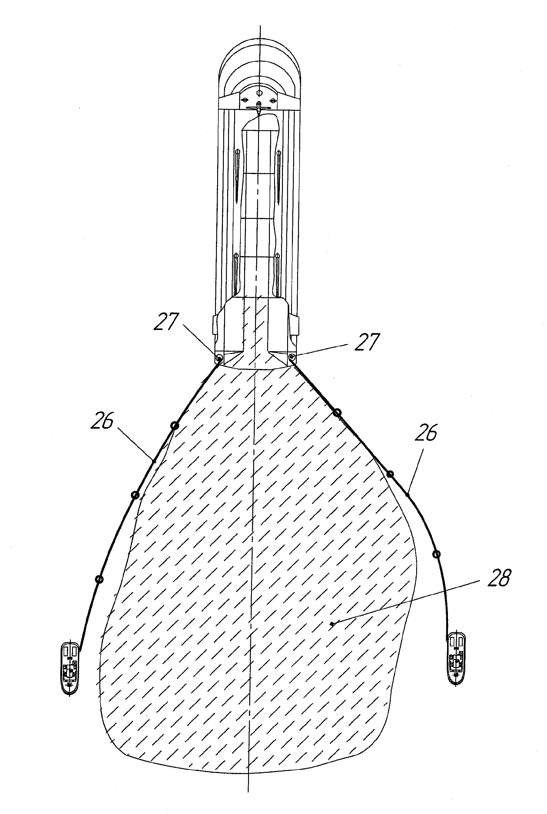
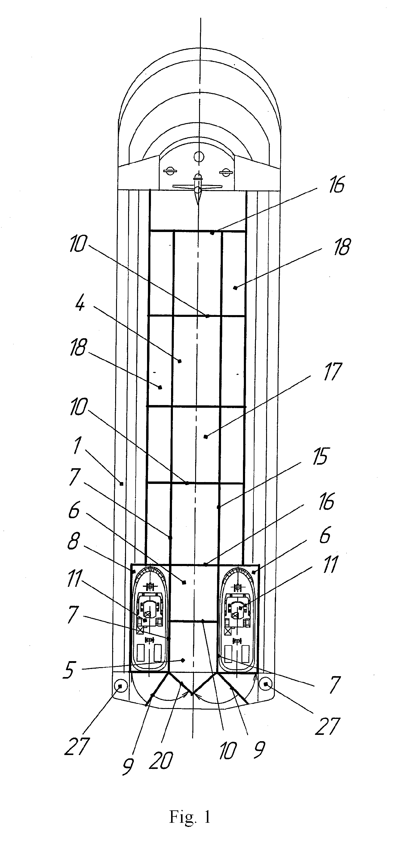
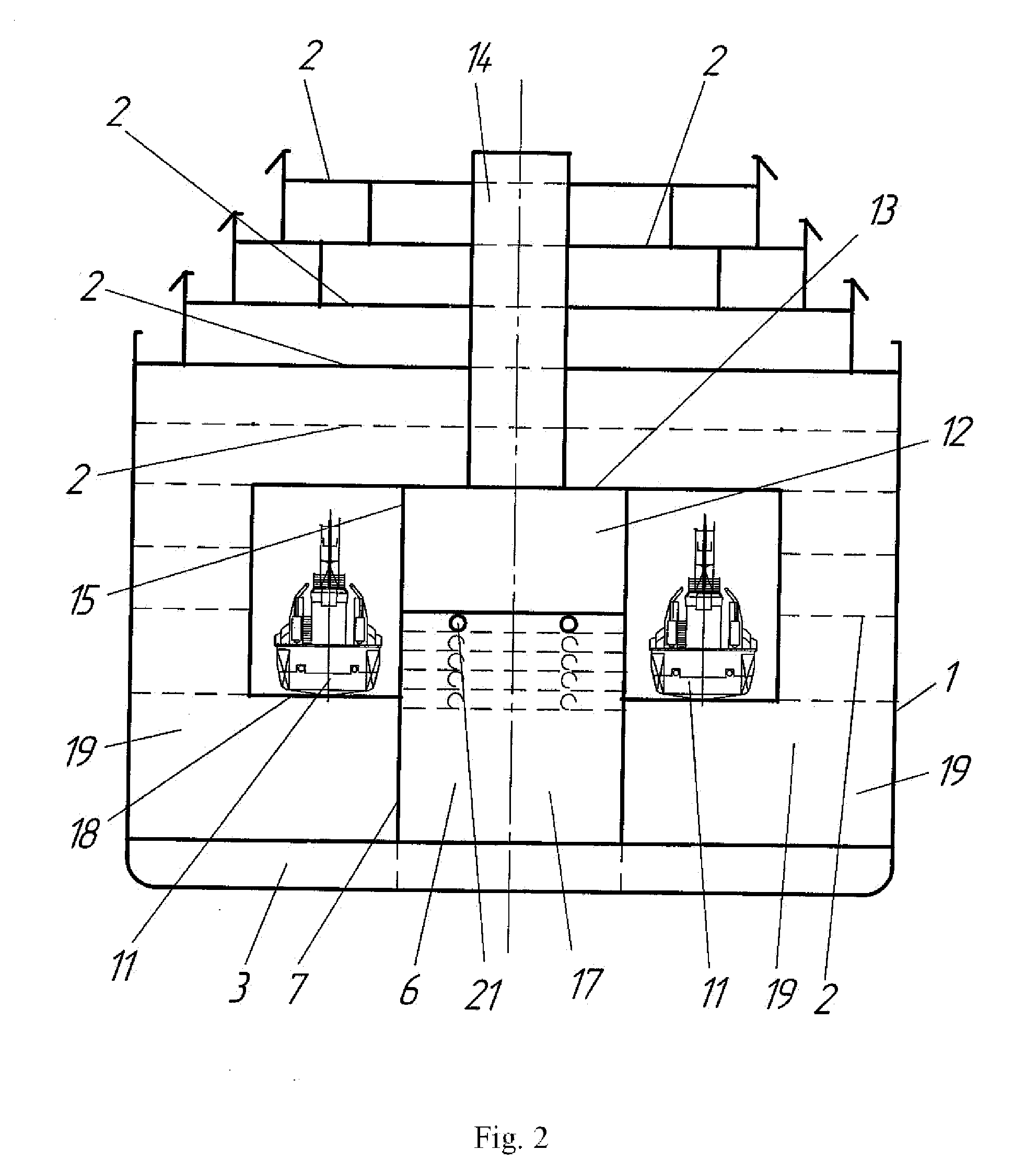
[0037]The device for skimming of oil on the sea is made as the dock vessel having a hull 1 with decks 2 and double bottom 3, the interior hull 1 is divided into two compartments: technological 4 and tow 5.

[0038]The tow 5 compartment is located in the after part of the hull 1 of dock vessel and made as a channel 6 framed by the walls 7 and two board 8 hangars equipped with separate 9 gates and bulkheads 10, at that, the width of the on-board hangar 8 is not less than that of the tug-boat 11 while the length is not less than that providing a placement of, at least, one tug-boat 11.

[0039]The technologic 4 compartment is made as a hangar 12 limited by a ceiling 13 fitted with ventilation shaft 14, side 15 and end 16 walls, at the bottom of a hangar 12, the central 17 channel is situated along the upper boundaries of the central 17 channel, the rack-ledges 18 with symmetrical location to the right and left, toward the hull, are placed on which the technological equipment (not shown in a ...


PUM


Abstract

The dock vessel has the tow compartment for placement of tug-boats, and technological compartment. The technological compartment is made as a hangar at the bottom of which a central channel is located, along its upper boundaries, the rack-ledges with symmetrical location to the right and left, toward the hull, are placed on which the technological equipment for the water-oil emulsion treatment is placed. Between the dock-vessel hull walls and side walls of the central channel, the containers for collection of the emulsified oil are placed. The central channel of the technological compartment is equipped with, at least, two bulkheads in which, the hermetically pluggable openings located at different levels are made. The floating boom is made as the sectional net sleeve filled with elastic porous adsorbent and provided with positive buoyancy in the top edge of doubled net forming the net sleeve and negative buoyancy at its lower edge.

Description

RELATED APPLICATIONS[0001]This Application is a Continuation application of International Application PCT / RU2012 / 000067, filed on Feb. 6, 2012, which in turn claims priority to Russian Patent Applications No. RU2011104469, filed Feb. 8, 2011, both of which are incorporated herein by reference in their entirety.FIELD OF THE INVENTION[0002]The invention relates to shipbuilding, in particular, vessels for skimming pollution from the water surface as well as environment protection and can be used for containment and removal of the stain of oil or oil-product including its large flow from any water surface. The application of the invention is possible for containment and removal of the accidental oil spills around the onshore loading terminals, marine mobile drilling platforms as well as for equipping the oil tankers, offshore drilling platforms.BACKGROUND OF THE INVENTION[0003]The oil garbage disposal vessel is known that comprises a hull with fore and aft ends, propulsive devices conne...

Claims


Application Information

Patent Timeline
Patent Type & Authority Applications(United States)
IPC IPC(8): E02B15/04
CPCE02B15/047E02B15/046B63B35/32B63B35/40B63B35/66Y02A20/204
Inventor ZOTOV, IGOR ALEKSEEVICHERYOMIN, YURIY VICTOROVICH
Owner ZOTOV IGOR A
Why Eureka
Try Eureka