
Linear motor, linear dynamo, reciprocation-type compressor driving system that is powered by linear motor, and charge system that uses linear dynamo

Inactive Publication Date: 2013-11-28
NIPPON PISTONRING CO LTD
View PDF0 Cites 18 Cited by
  • Summary
  • Abstract
  • Description
  • Claims
  • Application Information

AI Technical Summary

Benefits of technology

The patent aims to improve the efficiency of a linear type electric machine by decreasing the reluctance in the gap part. This will lead to a larger amount of magnetic flux which interlinks to the coil, resulting in better performance and power saving.

Problems solved by technology

However, there are a lot of cases where the miniaturization and the positional accuracy due to backlash of the gear, etc., become problems, when the gyration is mechanically converted into a rectilinear motion.
However, since the linear motors in the prior art are difficult to lessen their air-gaps, it has problems in terms of the high-torque and the high-efficiency.

Method used


Image

  • Linear motor, linear dynamo, reciprocation-type compressor driving system that is powered by linear motor, and charge system that uses linear dynamo
  • Linear motor, linear dynamo, reciprocation-type compressor driving system that is powered by linear motor, and charge system that uses linear dynamo
  • Linear motor, linear dynamo, reciprocation-type compressor driving system that is powered by linear motor, and charge system that uses linear dynamo

Examples


Embodiment Construction

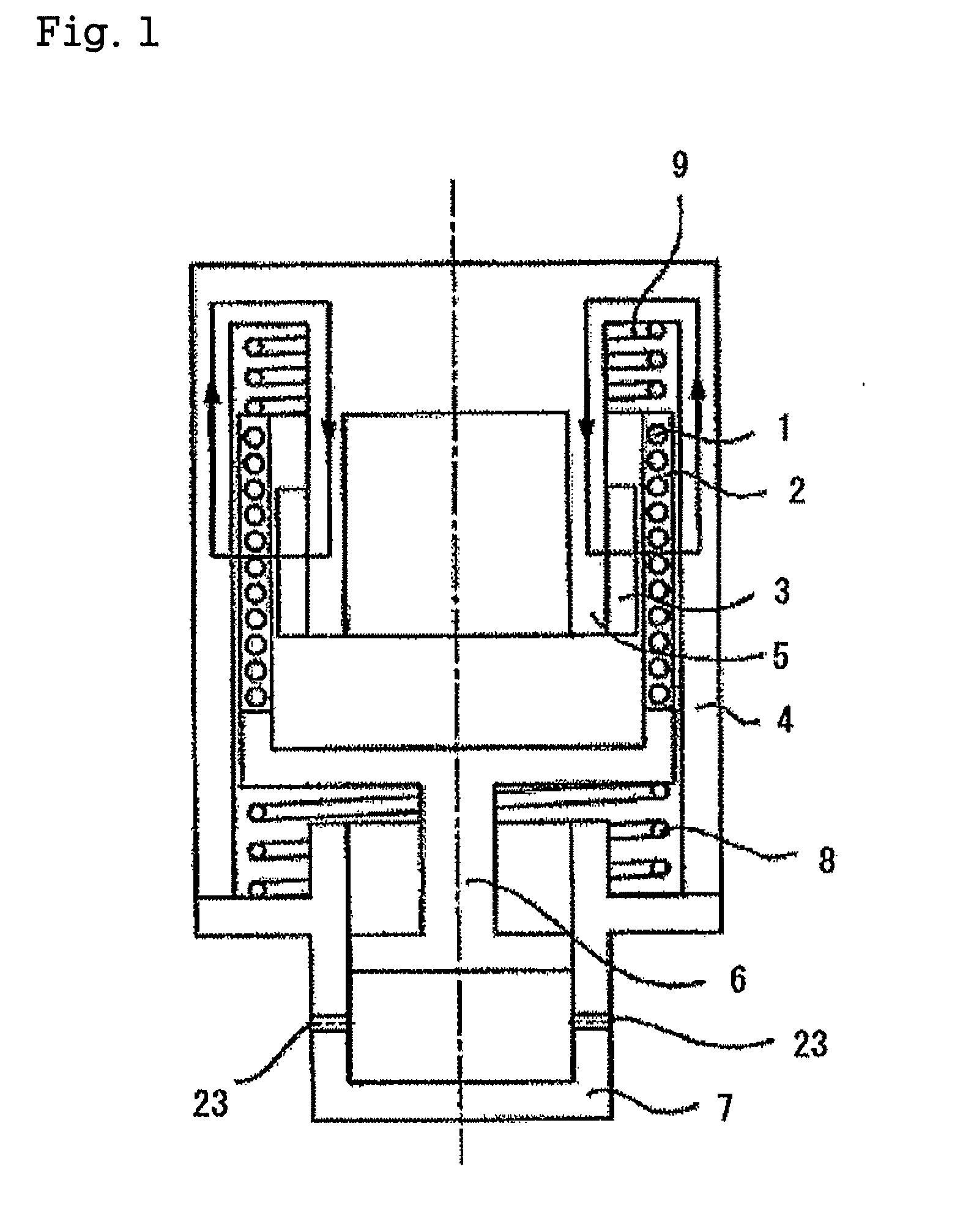
[0040]Now, the present invention will be described with reference to the drawings.

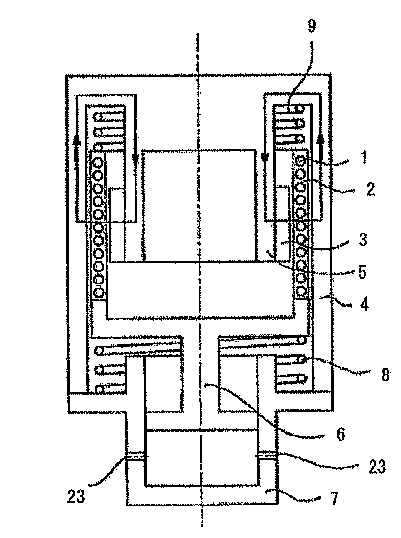
[0041]FIG. 1 is a sectional view of an embodiment of the present invention in the state of including a mobile axis.

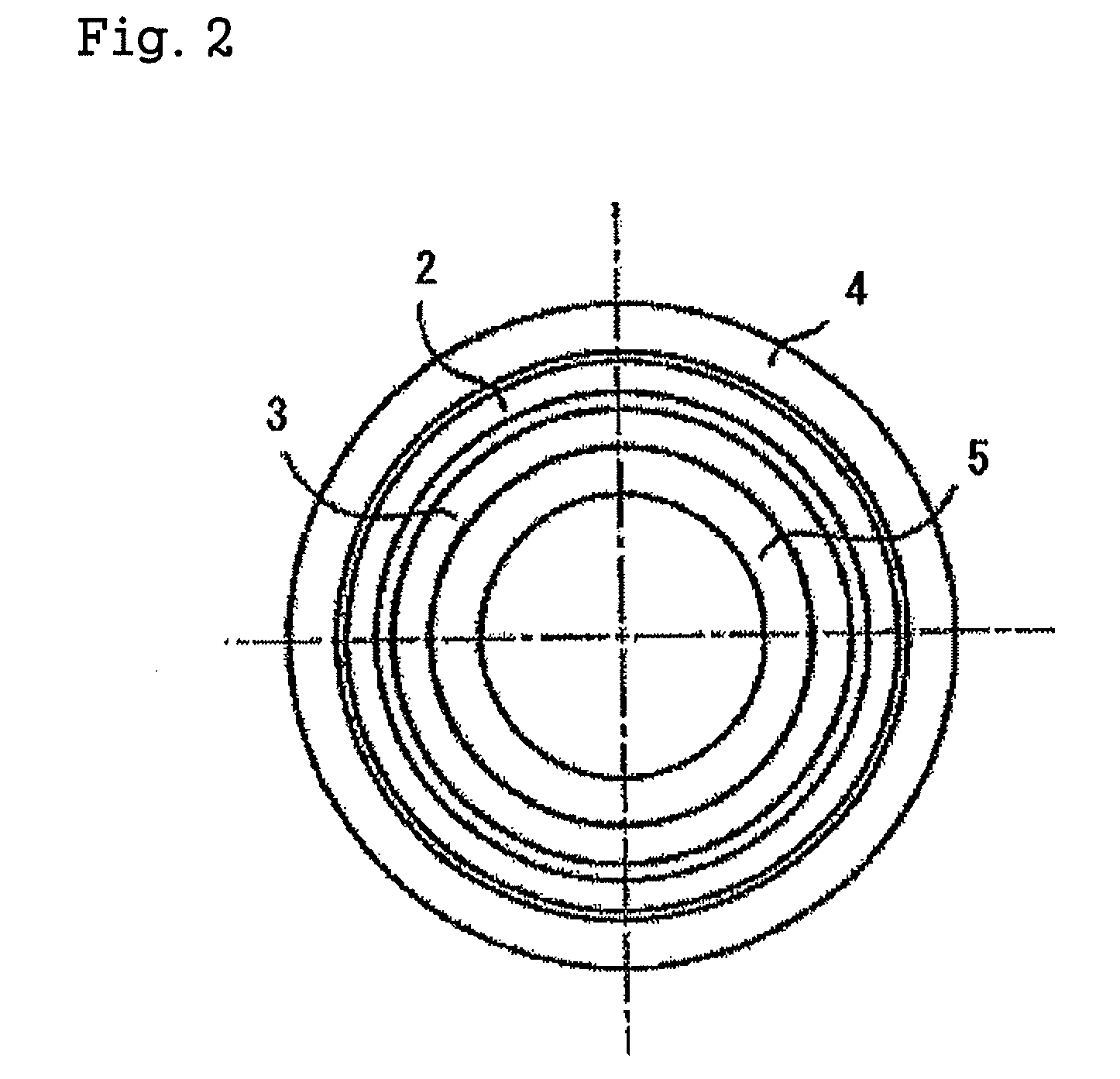
[0042]FIG. 2 is a view of the linear electric machine shown in FIG. 1, viewing from the mobile axial direction.

[0043]In FIG. 1 and FIG. 2, the numeral 1 denotes a coil that composes the armature part and that is a solenoid coil. The numeral 2 denotes a magnetic substance mobile part, which may be formed with a dust core, i.e., iron-powder compact magnetic core, which covers the coil 1. Alternatively, the magnetic substance mobile part may be formed with a resin which covers the coil 1 and which includes iron powder as a magnetic substance. The numeral 3 denotes a permanent magnet which forms the field magnet. The numeral 5 denotes a back yoke for the permanent magnet 3, and it is integrated with an outer circumference yoke 4 at the edge. The arrows shown in FIG. 1 indicates the flow of the...


PUM


Abstract

The disclosed is a linear motor which comprises an armature part including a coil, a field magnet part including a permanent magnet or an electromagnet, and a yoke part, in which the armature part is distributed in the field magnet part to excite the coil in the armature part, and which gives either the armature part or the field magnet part a rectilinear motion, wherein the armature part has a molded body in which the coil is covered with a magnetic substance, or has a structure in which a wall is formed on at least one of the internal circumference and the outer circumference of the coil with a magnetic cylindrical body.

Description

TECHNICAL FIELD[0001]This invention relates to a linear motor and a linear dynamo, as well as a reciprocation-type compressor driving system and a charge system using them.BACKGROUND ART[0002]There are a lot of usages for the electric motor and the dynamo that need a rectilinear motion. Particularly, the types in that the gyration with the rotation electric machine is mechanically converted into a rectilinear motion for instance, the rack & pinion and belt, etc., are large in number. However, there are a lot of cases where the miniaturization and the positional accuracy due to backlash of the gear, etc., become problems, when the gyration is mechanically converted into a rectilinear motion. In that case, the rectilinear motion type electric motor (hereinafter, it is referred to as “linear motor”.) is used.[0003]As for the compressors, there are a reciprocating piston-cylinder type driven with a linear motor and a scroll type driven with a rotation motor. The former tends to generate...

Claims


Application Information

Patent Timeline
IPC IPC(8): F03G7/08H02K35/04H02K33/18
CPCF03G7/08H02K33/18H02K35/04
Inventor SAKAMOTO, MASAFUMISATO, SHIGEYOSHITAKEGUCHI, SHUNSUKE
Owner NIPPON PISTONRING CO LTD
Learn More