
Alarm device for alerting hazardous conditions

a hazardous condition and alarm device technology, applied in fire alarms, fire alarm smoke/gas actuation, instruments, etc., can solve the problems of nuisance alarms, inconvenience for occupants, and inconvenience for residents, and achieve the effect of reducing the service life of batteries

Inactive Publication Date: 2013-11-28
BAKER LYNDON FREDERICK
View PDF6 Cites 15 Cited by
  • Summary
  • Abstract
  • Description
  • Claims
  • Application Information

AI Technical Summary

Benefits of technology

The patent describes a controller for a smoke alarm that can detect and respond to different types of sensors. The controller can enter a hush state to reduce nuisance alarms, or it can return to a normal state to increase sensitivity and provide better protection. The controller can also alert occupants when carbon monoxide levels are detected, even if no fire is present. The controller is an integrated circuit that saves power and is programmed to cycle in low power consumption modes. The patent also describes an optional secondary sensor for carbon monoxide detection.

Problems solved by technology

(NFPA “What you should know about Smoke Alarms” http: / / www.nfpa.org / assets / files / / PDF / Public%20Education / NFPASmokeAlarmFactSheet.Ddf) However ionization type smoke alarms tend to generate nuisance alarms when installed near kitchens.
Such nuisance alarms or sounds are very discomforting to the occupants.
However relocation might not be possible in a small dwelling as the most important location for a smoke alarm, just outside the bedroom, might be close to the kitchen.
Using photoelectric type smoke alarms reduces nuisance alarms but also reduces protection.
Unfortunately this, too, does not solve the problem since such buttons are beyond reach for most occupants due to positioning of the alarms on walls and ceilings.
Even those who can reach the hush button are still at risk of becoming desensitized to the smoke alarm if it sounds frequently.
However these proposals cannot be allowed to completely deactivate or significantly desensitize the alarm for an extended period of time.
Doing so would create an unacceptable risk for the occupant and would not meet fire safety standards.
This is because such motion Detectors are at risk of responding to pets or children or fire or other interference sources.
Unfortunately the lower sensitivity limit for ionization smoke alarms, allowed by most authorities, is not low enough to block many nuisance alarms that commonly occur near the kitchen.
(e.g. see Australian Standard 3786-1993, minimum sensitivity for ionization sensors=0.5 MIC×value) Thus, these proposals do not adequately solve the problem.
Furthermore, because of the technology employed, all these proposals require at least two separate packages for implementation and are not suitable for drawing their power from the smoke alarm's own battery.
This reduces their aesthetics and makes them expensive and hard to install.
This could cause alarm desensitization for the wrong reason.
Although this threshold is acceptable to fire safety authorities, it will nevertheless result in a significant loss in smoke alarm sensitivity which unnecessarily continues around the clock.
Alternatively, if the smoke alarm sensitivity is maintained, it will suffer from a significant nuisance alarm problem near the kitchen.
These devices offer improvements but must still compromise on performance to mitigate nuisance alarms near the kitchen.
An additional problem manifests itself during low battery conditions of ionization and photoelectric smoke alarms as well as other types of alarms.
As a result, the occupant often cannot postpone the battery change.
Because most dwellings are fitted with multiple smoke alarms the faulty smoke alarm can be very hard to find.
However, as mentioned earlier, the proximity detector will be out of reach for other occupants.
Thus this method will not always solve the low battery alert problem.

Method used


Image

  • Alarm device for alerting hazardous conditions
  • Alarm device for alerting hazardous conditions
  • Alarm device for alerting hazardous conditions

Examples


Embodiment Construction

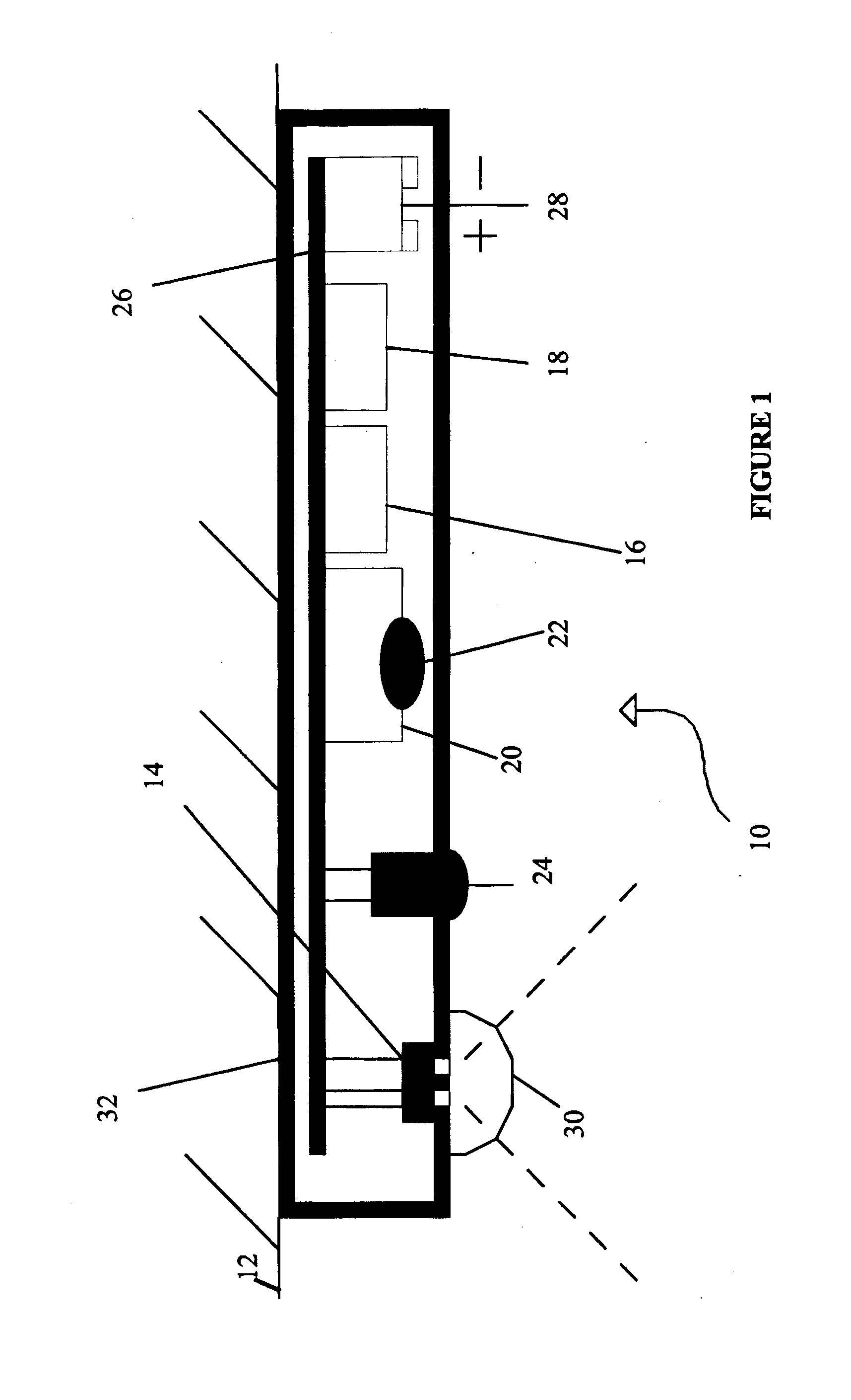
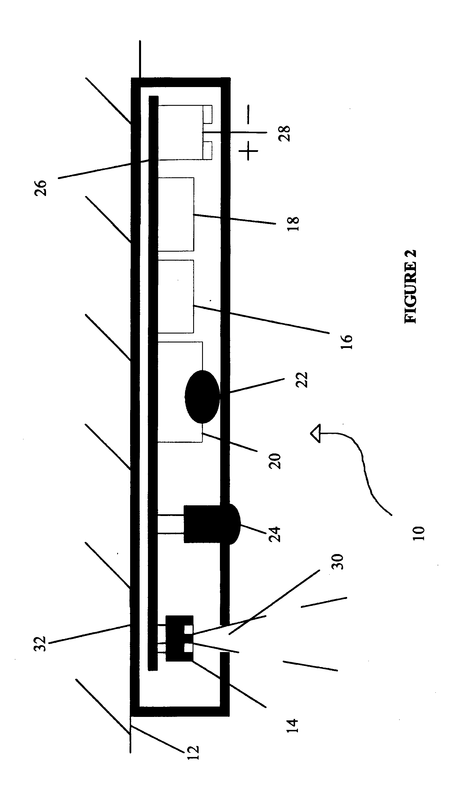
[0031]Referring to the drawings and initially to FIG. 1 there is illustrated in plan cut-away view an embodiment of the alarm device 10 according to the present invention. As shown, the device 10 is fixed to a ceiling 12 of a building. The device can be fixed to the ceiling by any fixing means.

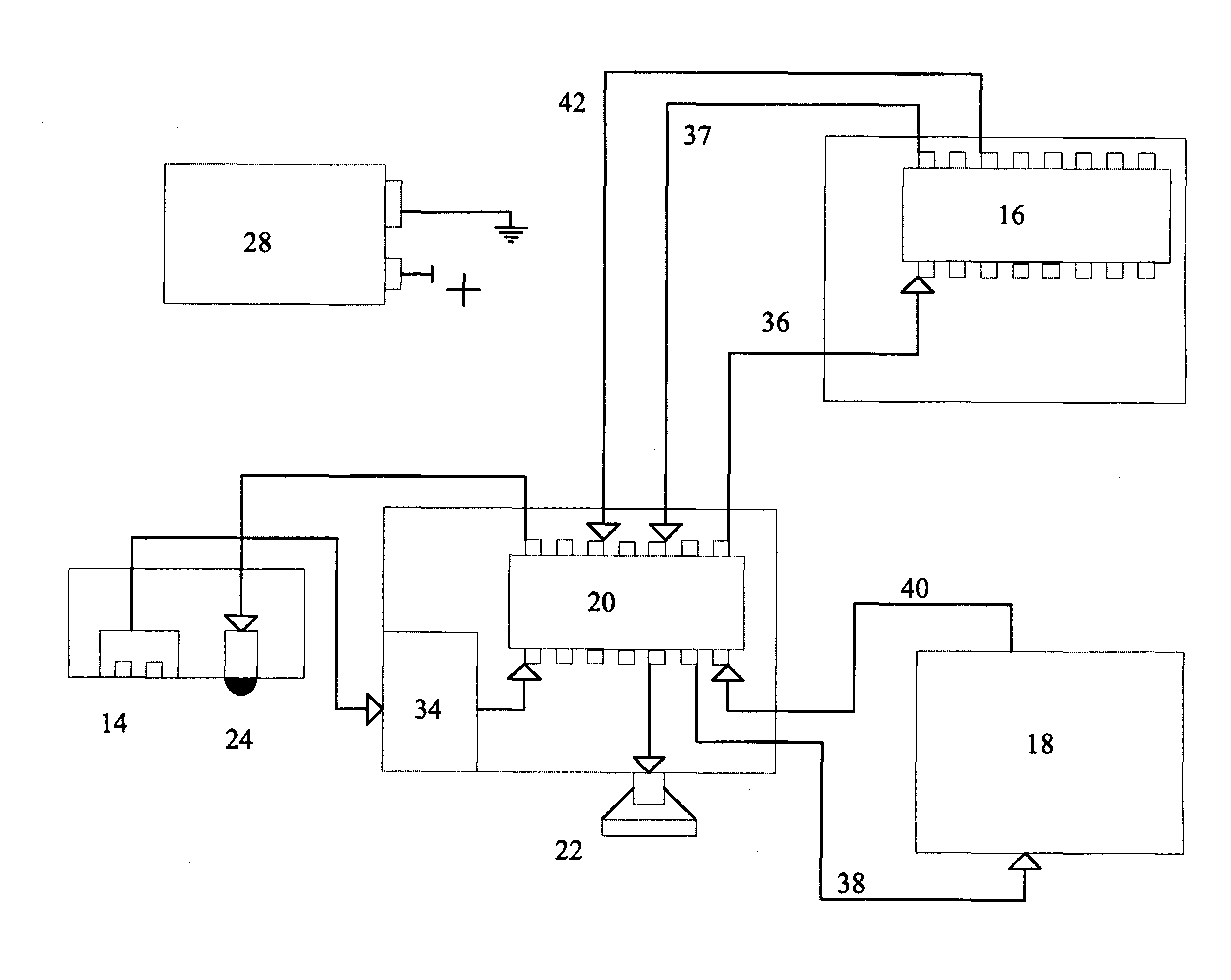
[0032]The device 10 of this embodiment is for alerting occupants in the building in the event of fire. The device has a motion detection module 14 in the form of a passive infrared motion detector (PID), a primary sensing module 16 in the form of an ionization sensor, a secondary sensing module 18 which can be a photoelectric sensor or a carbon monoxide (CO) sensor, a controller 20 arranged to activate an audible alarm module 22 in the form of a horn on receiving an alarm signal from the sensors. The controller has a timer (not shown) and is arranged to be in a hush state for a preset time period (10 minutes for this embodiment) upon receiving a motion signal from the PID. In both the Normal S...


PUM


Abstract

Provided is a smoke alarm device (10) comprising a motion detection module (14) for generating a motion detection signal on detecting human motion within a detection zone, a primary sensing module (16) arranged to generate an alarm signal where the primary sensing module senses a hazardous condition, at least one secondary sensing module (18) arranged to generate an alarm signal where the secondary sensing module senses a hazardous condition, and a controller (20) arranged to activate an audible alarm module (22) on receiving any of said alarm signals. The controller has a timer and is arranged to be in a hush state for a preset time period upon receiving said motion detection signal. In said hush state, the controller is arranged to activate the audible alarm module upon receiving alarm signals from both the primary and the at least one secondary sensing modules, or from either the primary or any one of said at least one secondary sensing module.

Description

FIELD OF THE INVENTION[0001]THIS INVENTION relates to an alarm device for alerting hazardous conditions in a building, and, in particular but not limited thereto, a smoke alarm device having a primary smoke sensor module and at least one secondary sensor for sensing gas and / or particles in smoke.BACKGROUND OF THE INVENTION[0002]Ionization type smoke alarms and photoelectric type smoke alarms are commonly used in residential buildings. Each type has its advantages. Ionization type smoke alarms generally respond faster to flaming fires, while photoelectric (optical) type smoke alarms generally respond faster to smouldering fires. Although both ionization and photoelectrical smoke alarms meet the standards established by the fire protection industry, for improved protection authorities such as the National Fire Protection Association (NFPA) recommend that both types be used in the home. (NFPA “What you should know about Smoke Alarms” http: / / www.nfpa.org / assets / files / / PDF / Public%20Educa...

Claims


Application Information

Patent Timeline
Patent Type & Authority Applications(United States)
IPC IPC(8): G08B17/10
CPCG08B17/10G08B17/11G08B17/117G08B29/183G08B19/00G08B23/00
Inventor BAKER, LYNDON FREDERICK
Owner BAKER LYNDON FREDERICK
Learn More