Method and Apparatus for Analyzing the Spectrum of Radio-Frequency Signals Using Unamplified Fiber Optic Recirculation Loops

a fiber optic recirculation loop and radio frequency signal technology, applied in electrical equipment, multiplex communication, antennas, etc., can solve the problems of high-speed dsp systems that are very costly to manufacture, operate and maintain, and communication is transmitted across various frequencies

Active Publication Date: 2013-11-28
ARMY US SEC THE
View PDF10 Cites 25 Cited by
  • Summary
  • Abstract
  • Description
  • Claims
  • Application Information

AI Technical Summary

Benefits of technology

[0007]Embodiments of the present invention relate to a method and an apparatus for generating a frequency spectrum of an RF signal comprising a gate switch for generating a series of pulses from a laser of wavelength lambda (λ) modulated by an input RF signal, a first fiber optical loop for circulating a first percentage of a first pulse of the series of pulses from the gate switch, for a predetermined number of cycles n where each cycle takes time t1, a second fiber optical buffer delay loop for conducting a second percentage of the first pulse for a predetermined number of cycles “k”, where each cycle takes time t2, where t...

Problems solved by technology

However, difficulties arise when a communication is transmitted across various frequencies, i.e., frequency hopping is employed, in the form of short RF pulses where each broadcast is on a different frequency.
Such high speed DSP systems are very costly to manufacture, ope...

Method used


Image

  • Method and Apparatus for Analyzing the Spectrum of Radio-Frequency Signals Using Unamplified Fiber Optic Recirculation Loops
  • Method and Apparatus for Analyzing the Spectrum of Radio-Frequency Signals Using Unamplified Fiber Optic Recirculation Loops
  • Method and Apparatus for Analyzing the Spectrum of Radio-Frequency Signals Using Unamplified Fiber Optic Recirculation Loops

Examples


Embodiment Construction

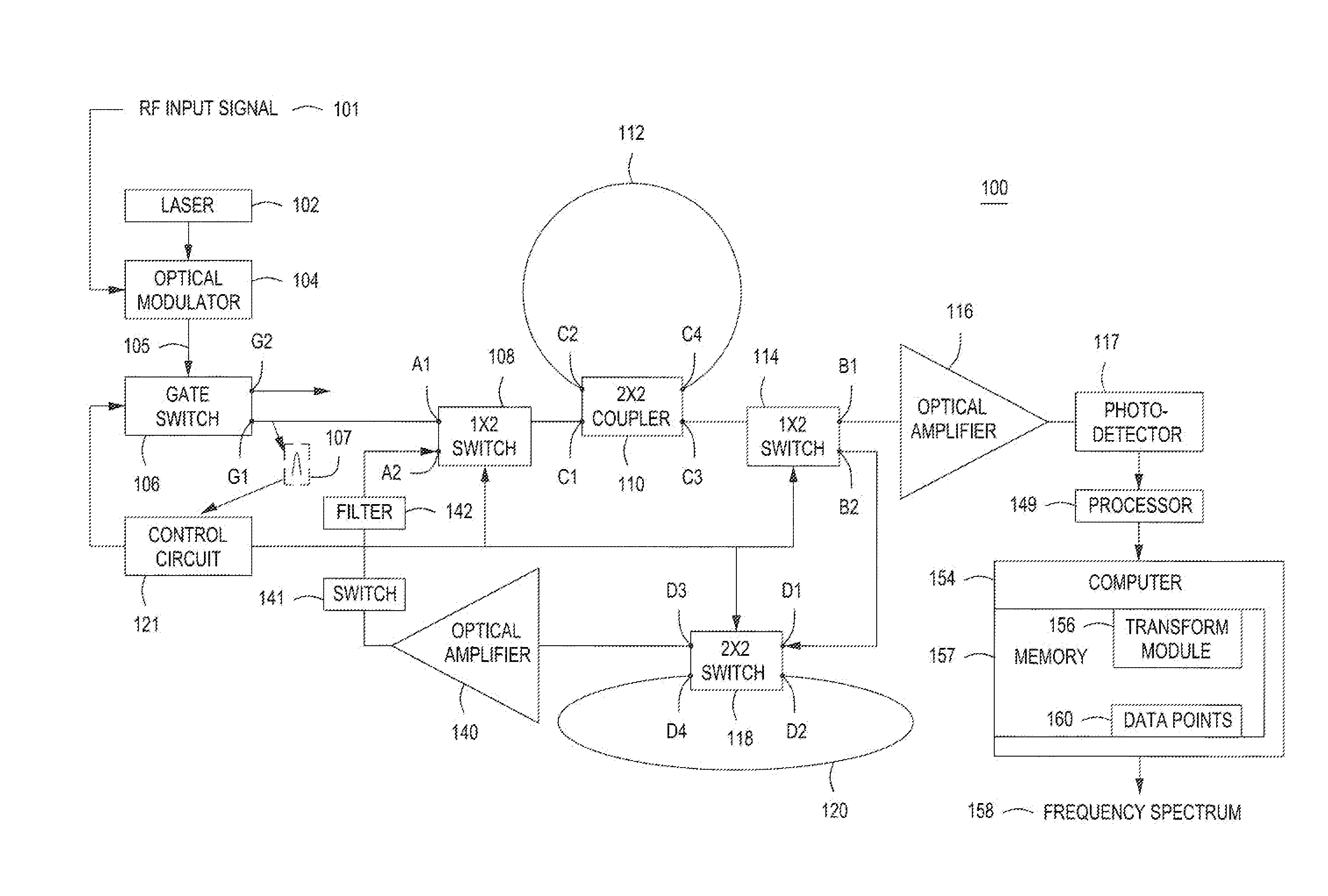
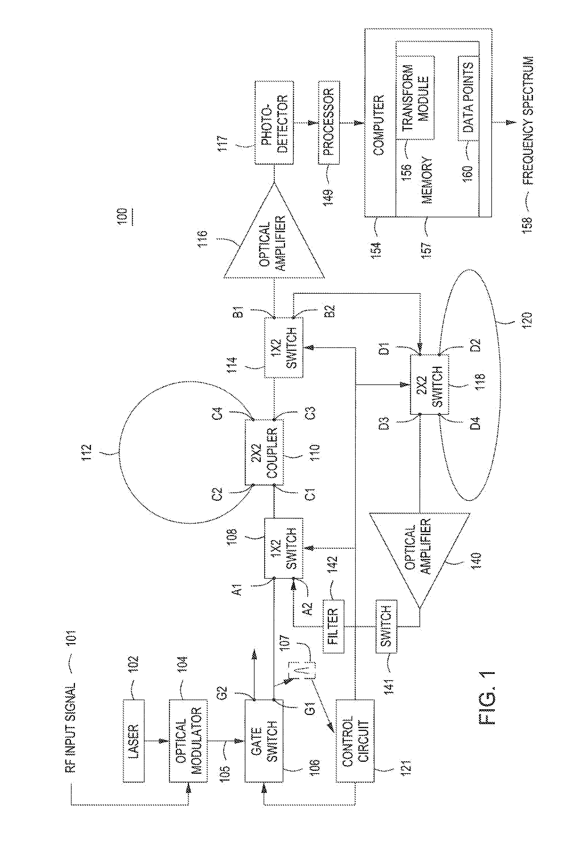
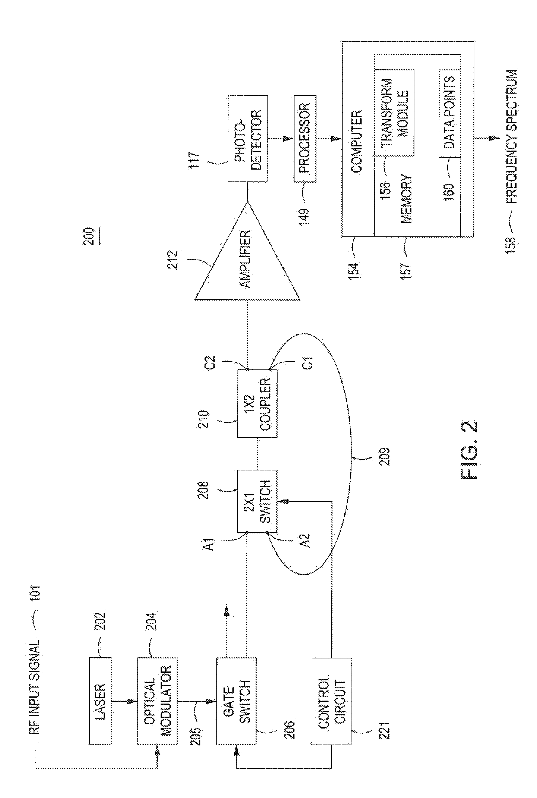
[0013]Embodiments of the present invention comprise an apparatus for generating a large number of re-circulated replica signal pulses in the time domain from a single input optical pulse that carry a RF signal with two side bands while avoiding noise by use of an unamplified, extreme low-loss, fiber-optic recirculation loop circuit. In some embodiments fiber-optic recirculation loop circuit comprises two fiber optical loops, where one fiber optical loop recycles and introduces a buffer delay in the original input pulse to augment the intensity of the pulse signal in the other fiber optical loop. Each replica pulse carries two copies of the RF signal, the copies having a relative time delay due to the chromatic dispersion of the fiber optical loop. The replica signal pulses are then coupled to a photodetector to obtain the RF signal that is expanded in time as a series of delayed pulses that may be later correlated. A processor is configured to perform a Fast-Fourier Transform (FFT),...


PUM


Abstract

An apparatus for generating a frequency spectrum of an RF signal comprising a gate switch for generating a series of pulses from a laser of wavelength lambda modulated by an input RE signal, a first fiber optical loop for circulating a first percentage of a first pulse of the series of pulses from the gate switch, for a predetermined number of cycles n where each cycle takes time t1, a second fiber optical loop for conducting a second percentage of the first pulse for predetermined number of cycles “k”, where each cycle takes time t2, where t2*k=t1*n, a first switch with a first state for coupling the first pulse from the gate switch to a coupler, the coupler coupling the first pulse into the first fiber optical loop and tapping replicas of the pulse from the first fiber optical loop, and a second state for coupling the second percentage of the first pulse to the coupler to increase intensity of the tapped replica pulses, a processor for correlating the replicas of the pulse with each other to produce a set of data points comprising a plurality of multiplexed correlated pulses and transforming the data points into a channelized frequency spectrum of the input RF signal.

Description

GOVERNMENT INTEREST[0001]Governmental Interest—The invention described herein may be manufactured, used and licensed by or for the U.S. Government.FIELD OF INVENTION[0002]Embodiments of the present invention generally relate to radio-frequency receiving system and, more particularly, to a method and apparatus for analyzing the spectrum of radio-frequency signals using unamplified fiber optic recirculation loops.BACKGROUND OF THE INVENTION[0003]Typically, public radio-frequency (RF) communications are transmitted at a preconfigured frequency so that a receiver can tune to the particular frequency and receive the communications. In contrast, private communications and military RF systems are transmitted across multiple frequencies (e.g., using frequency hopping and / or spread spectrum techniques) in a short time window. In some instances, these private communications need to be captured by unintended receivers, e.g., law enforcement agencies, military organizations and the like. Howeve...

Claims


Application Information

Patent Timeline
IPC IPC(8): H04Q11/00
CPCH04Q11/0003H04B2210/006H01Q3/2676
Inventor ZHOU, WEIMIN
Owner ARMY US SEC THE
Why Eureka
Try Eureka