Applicator unit for a cosmetic unit and cosmetic unit with an applicator unit of this type

Inactive Publication Date: 2013-11-28
H & M GUTBERLET
View PDF6 Cites 3 Cited by
  • Summary
  • Abstract
  • Description
  • Claims
  • Application Information

AI Technical Summary

Benefits of technology

[0021]An applicator unit, in which the stop element has a sleeve portion and a contact face, comprises a hollow sleeve portion, which, in particular, is configured concentrically with respect to the applicator longitudinal axis and is connected to the applicator support body. In particular, a connecting portion connecting the sleeve portion to the applicator support body has a contact face, which is used to apply a spring element. The contac

Problems solved by technology

The applicator unit can be produced in

Method used


Image

  • Applicator unit for a cosmetic unit and cosmetic unit with an applicator unit of this type
  • Applicator unit for a cosmetic unit and cosmetic unit with an applicator unit of this type
  • Applicator unit for a cosmetic unit and cosmetic unit with an applicator unit of this type

Examples


Embodiment Construction

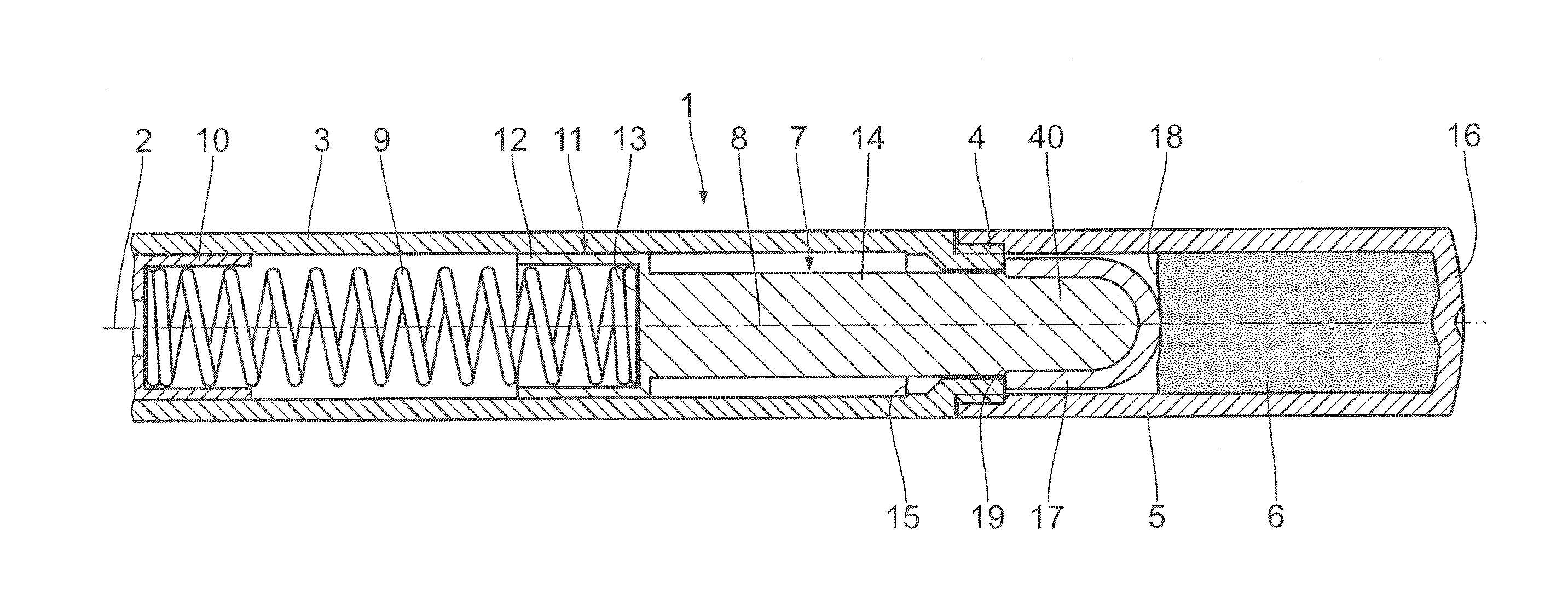
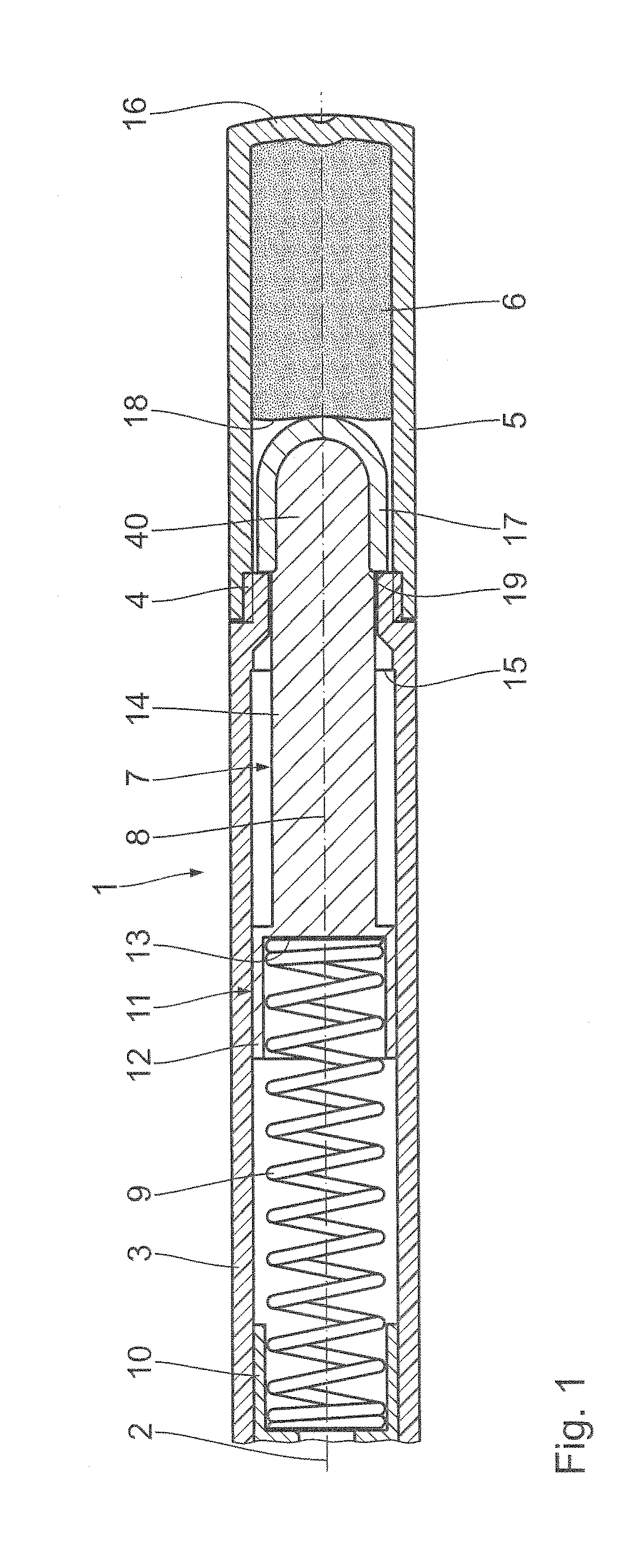
[0036]A cosmetic unit shown partially in FIG. 1 is configured as a cosmetic pencil 1 and comprises a housing 3 having a housing longitudinal axis 2. The housing 3 is configured as a sleeve and closed at one end, shown on the right in FIG. 1, with a cap 5 screwed on by means of an internal thread 4. A supply of a cosmetic product 6 is provided in the cap 5. The cosmetic product 6 is provided in a pasty and / or powdery mass.

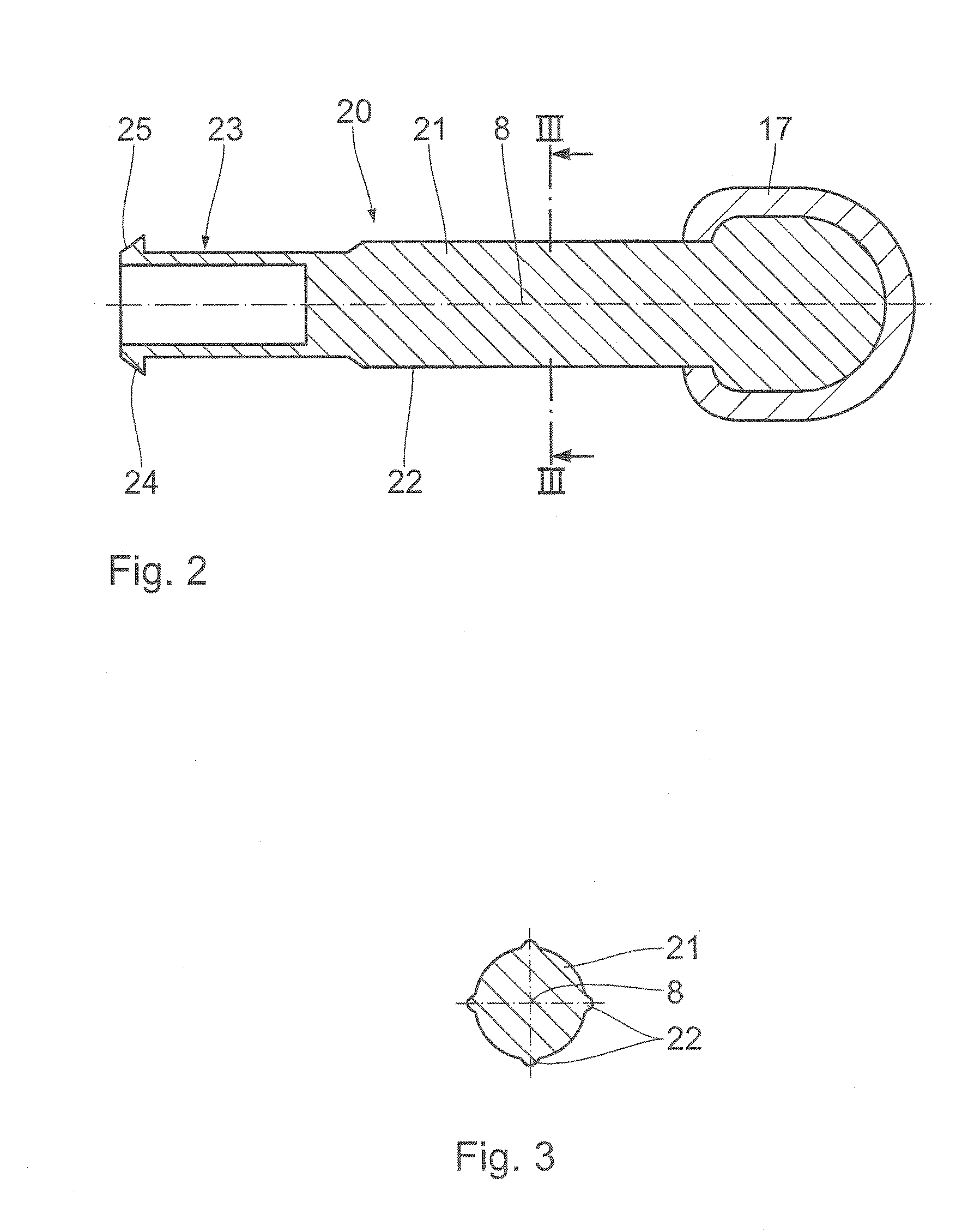
[0037]An applicator unit 7 with an applicator longitudinal axis 8 is arranged concentrically with respect to the housing longitudinal axis 2 in the housing 3. The applicator unit 7 can be displaced along the housing longitudinal axis 2 in the housing 3. For this purpose, a compression spring 9, shown on the left in FIG. 1 is provided, which is supported on an, in particular, screwed-in receiver 10 in the axial direction along the housing longitudinal axis 2.

[0038]The applicator unit 7 has a bowl-shaped stop element 11. The stop element 11 comprises a hollow sleeve p...


PUM


Abstract

An applicator unit for a cosmetic unit comprises a substantially cylindrical applicator support body with an applicator longitudinal axis and an applicator arranged on an applicator head of the applicator support body to apply a cosmetic product, the applicator unit being configured in one piece.

Description

CROSS-REFERENCES TO RELATED APPLICATIONS[0001]This application claims the priority of German Patent Application, Serial No. 10 2012 208 918.7, filed May 25, 2012, pursuant to 35 U.S.C. 119(a)-(d), the content of which is incorporated herein by reference in its entirety as if fully set forth herein.FIELD OF THE INVENTION[0002]The invention relates to an applicator unit for a cosmetic unit and a cosmetic unit with an applicator unit of this type.BACKGROUND OF THE INVENTION[0003]An applicator for liquid or pasty media, in particular decorative cosmetics such as mascara, is known from DE 101 02 219 A1. A mascara brush of this type has a core, on which a carrier sleeve is held. The production of a mascara brush of this type is complicated and laborious.[0004]A device for storing and applying a cosmetic product is known from DE 60 2004 007 435 T2. The device comprises a holder and a band, which is fastened to the holder and on which a large number of application elements are provided. The...

Claims


Application Information

Patent Timeline
IPC IPC(8): A45D40/20
CPCA45D40/20A45D33/36A45D34/04A45D34/045A45D40/10A45D40/26A45D40/28A45D2200/1009A45D2200/1018
Inventor GUTBERLET, DETLEV
Owner H & M GUTBERLET
Why Eureka
Try Eureka