
Distributed low-power wireless monitoring

a wireless monitoring and low-power technology, applied in power management, instruments, high-level techniques, etc., can solve the problems of system power consumption, data sampling, wireless transmission, wireless transmission, etc., to reduce power consumption, reduce the duration of wireless transmission, and minimize power consumption

Active Publication Date: 2013-11-28
PORTLAND STATE UNIV +1
View PDF2 Cites 81 Cited by
  • Summary
  • Abstract
  • Description
  • Claims
  • Application Information

AI Technical Summary

Benefits of technology

The present invention provides a compact, power-efficient, programmable data acquisition instrument that can log data based on a comparison of a current sensed value with a past sensed value or baseline value and a configurable parameter. The data logger is activated based on predetermined differences between two sensed values, which reduces power consumption. The invention also includes a data compression feature that reduces the duration of wireless transmission. The invention further presents a cloud-based software program that can perform more power-hungry data analysis using internet-based software programs. These key features combine as one complete data acquisition system to enable high performance and advanced data analysis.

Problems solved by technology

Current distributed wireless monitoring systems experience a tradeoff between frequency of sampling / logging and energy consumption.
On the other hand, data sampling, logging, and wireless transmission all consume power which is limited in battery operated remote sensor devices.
Unfortunately, current systems use remote sensor devices that are not power efficient because they are built of components (sensors, microprocessor, logger, radio, antenna, and power supply) that are packaged and sold separately.

Method used


Image

  • Distributed low-power wireless monitoring
  • Distributed low-power wireless monitoring
  • Distributed low-power wireless monitoring

Examples


Embodiment Construction

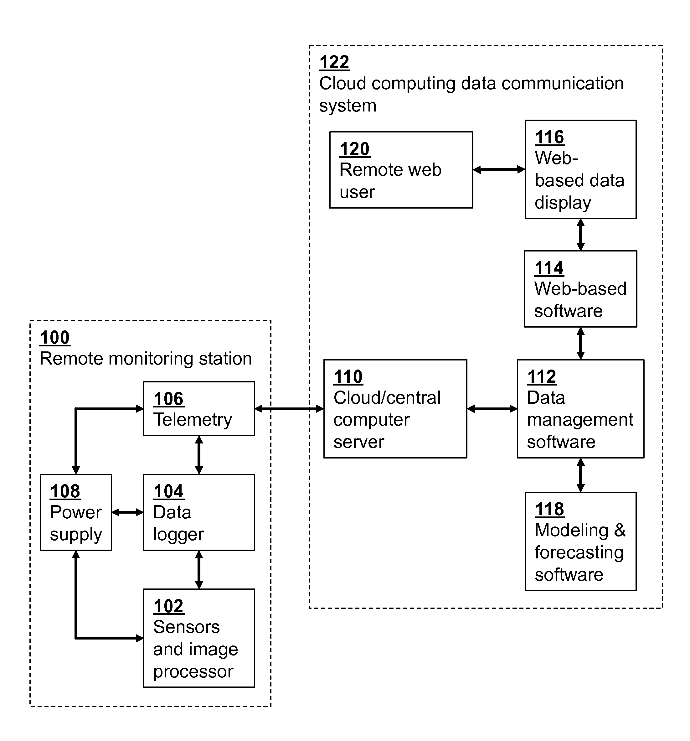
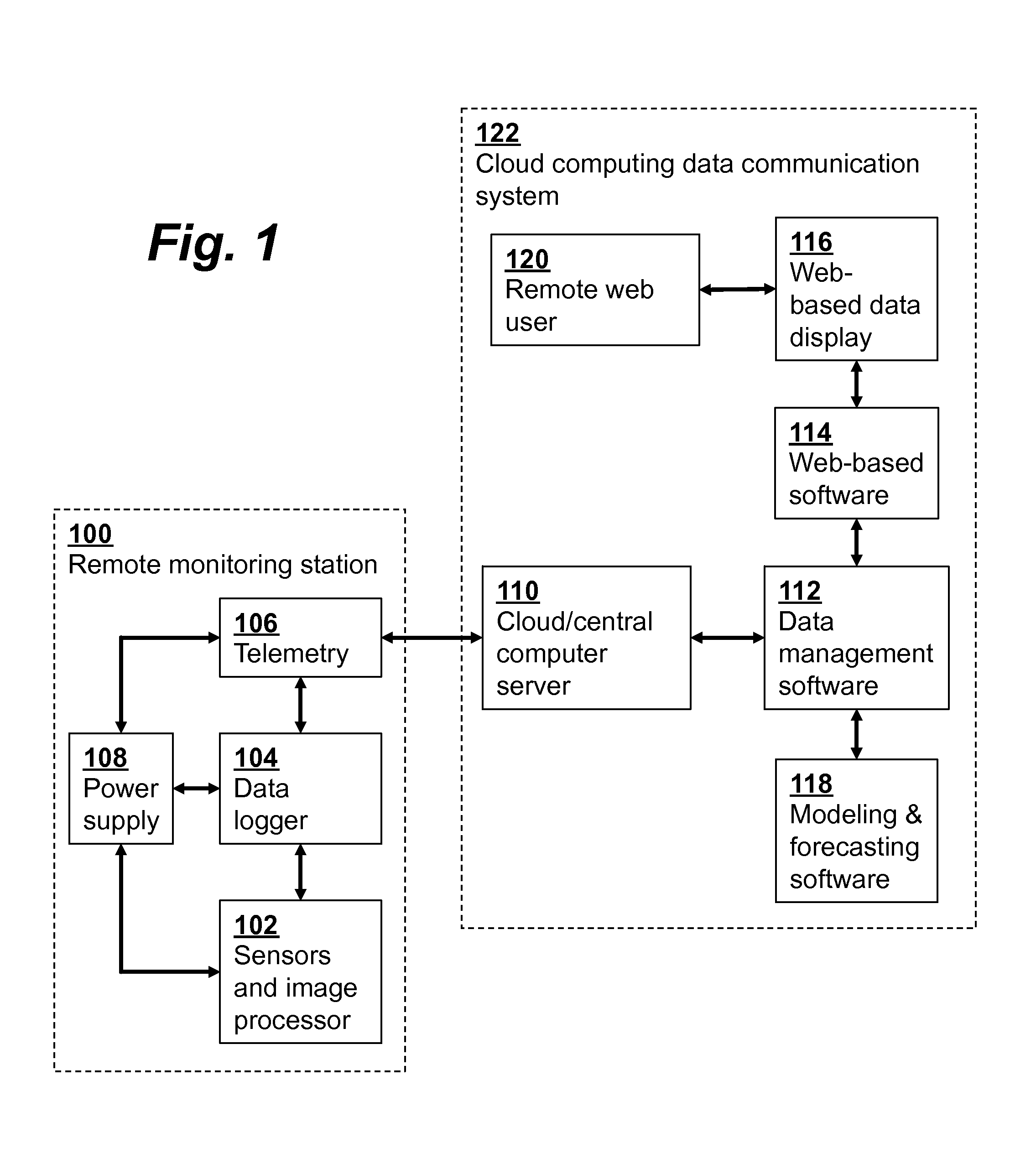
[0021]An embodiment of a distributed wireless monitoring system according to the invention is shown in FIG. 1. The system includes a cloud computing data communication system 122 which includes a computer server 110 in communication with multiple distributed remote monitoring devices, such as station 100. The remote station 100 includes sensors 102 (which may include an image processor) a data logger 104, telemetry 106, and power supply 108. Measurements using sensors 102 are encoded using data compression in order to reduce power consumption from transmission and storage. The compact data representation is decoded by the cloud server 110 after upload. The sensors 102 and data logger 104 are event activated based on predetermined comparison thresholds between one or several independent sensors, resulting in added power conservation. The event triggering thresholds may be remotely configured via the cloud server 110. The remote station 100 also may be configured to provide alarm cond...


PUM


Abstract

A distributed wireless monitoring system with low-power remote sensors includes data encoding / compression at sensors to reduce power use from transmission and storage, event activated operation / data logging, remote configuration of event triggering thresholds and correlation templates, distributed processing capabilities, and sensor clock synchronization from a network time service.

Description

CROSS-REFERENCE TO RELATED APPLICATIONS[0001]This application is a continuation-in-part of U.S. patent application Ser. No. 13 / 605,828 filed Sep. 6, 2012, which claims priority from U.S. Provisional Patent Application 61 / 531,579 filed Sep. 6, 2011, both of which are incorporated herein by reference.FIELD OF THE INVENTION[0002]The present invention relates generally to wireless monitoring systems. More specifically, it relates to methods for distributed low-power wireless monitoring.BACKGROUND OF THE INVENTION[0003]Distributed wireless monitoring systems have many important applications including deployment in third-world communities that currently lack access to safe drinking water and / or use biomass for their daily energy needs. Remote monitoring systems are a useful method to ensure the success of water, energy and infrastructure projects conducted in their communities. Rather than infrequent human measurement, remote monitoring systems deployed in these communities automatically ...

Claims


Application Information

Patent Timeline
Patent Type & Authority Applications(United States)
IPC IPC(8): H02J4/00
CPCH04W52/0216H04W52/0219Y02B60/50H02J4/00Y02D30/70
Inventor THOMAS, EVAN A.FLEMING, MICHAEL E.SPILLER, WILLIAM K.CHAN, CHUN KITZUMR, ZDENEK
Owner PORTLAND STATE UNIV
Learn More