Magnetic barrier for minimizing demagnetization in bi-permanent magnet synchronous machines

a magnet barrier and demagnetization technology, applied in the direction of dynamo-electric machines, magnetic circuit rotating parts, magnetic circuit shapes/forms/construction, etc., can solve the problems of increasing the overall price of the motor, high cost of rare earth magnet use, etc., to reduce the content and weight reduce the overall cost of the motor, and reduce the number of rare earth magnets used

Active Publication Date: 2013-12-05
GM GLOBAL TECH OPERATIONS LLC
View PDF0 Cites 32 Cited by
  • Summary
  • Abstract
  • Description
  • Claims
  • Application Information

AI Technical Summary

Benefits of technology

[0004]An advantage of an embodiment is the reduction in the content and weight of rare earth magnets which reduces the overall cost of the motor. The interior permanent synchronous machine utilizes bi-permanent magnets (i.e., the combination of two or more different types of magnet materials) for reducing the number of rare earth magnets utilized in the rotor. A combination of rare earth magnets and ferrite magnets, or magnets of a same material composition having different magnetic field strengths, is utilized in the rotor in a multilayer manner. A unique magnetic barrier design between magnets of different magnetic field strength increases a reluctance which minimizes the magnetic flux originating from the magnet with the weaker magnetic field from flowing toward the magnet having the stronger magnetic field. As a result, a demagnetization of the weaker magnets is minimized.

Problems solved by technology

However, using rare earth magnets in a motor is costly and increases the overall price of the motor.

Method used


Image

  • Magnetic barrier for minimizing demagnetization in bi-permanent magnet synchronous machines
  • Magnetic barrier for minimizing demagnetization in bi-permanent magnet synchronous machines
  • Magnetic barrier for minimizing demagnetization in bi-permanent magnet synchronous machines

Examples


Embodiment Construction

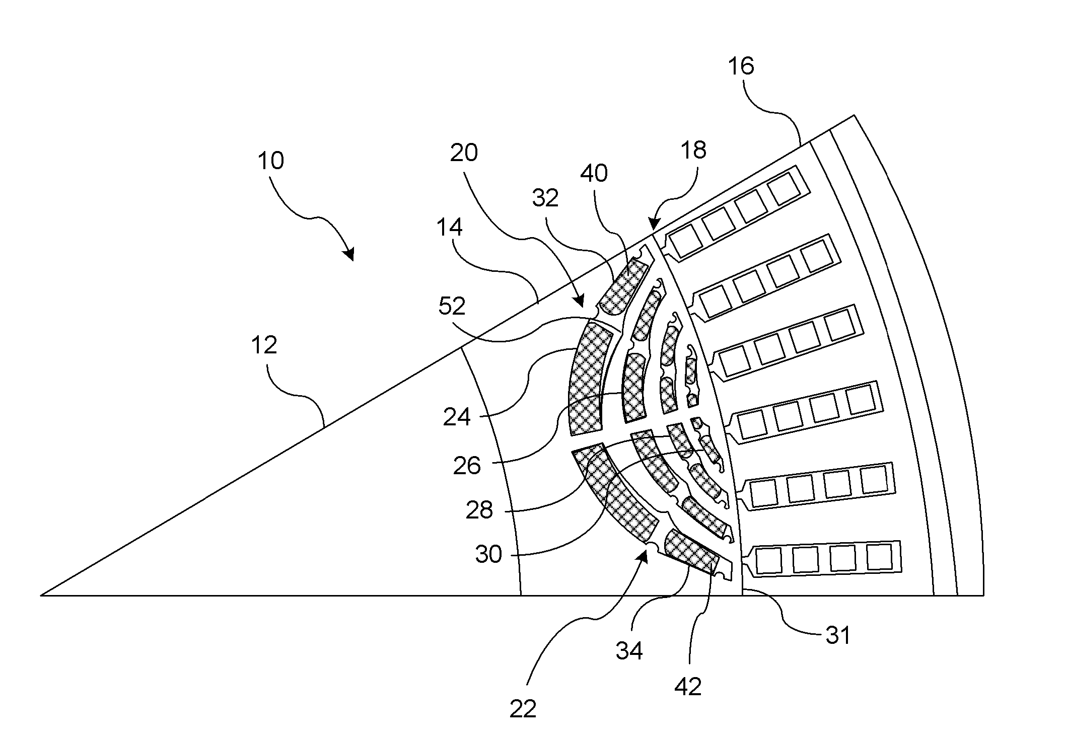
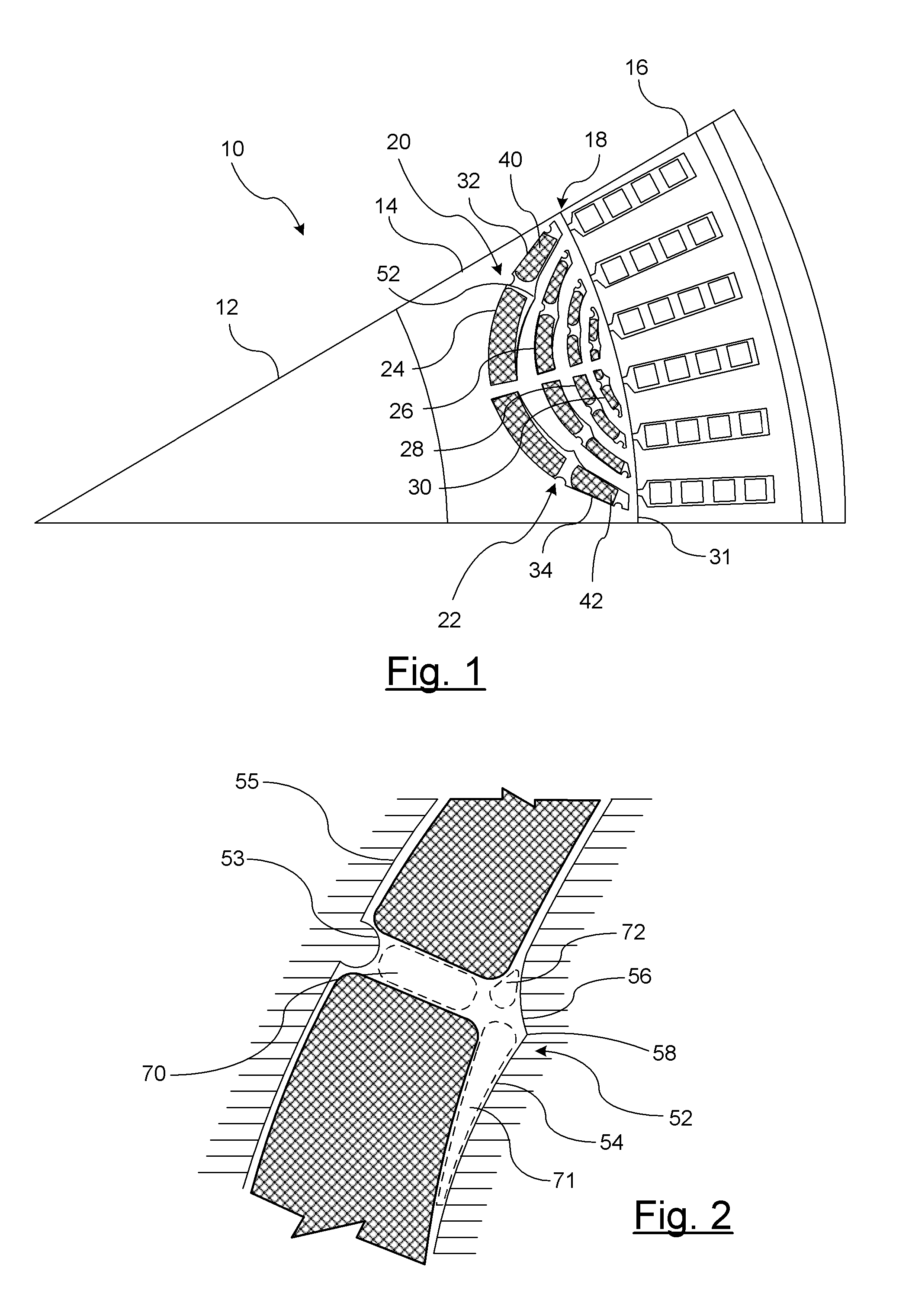
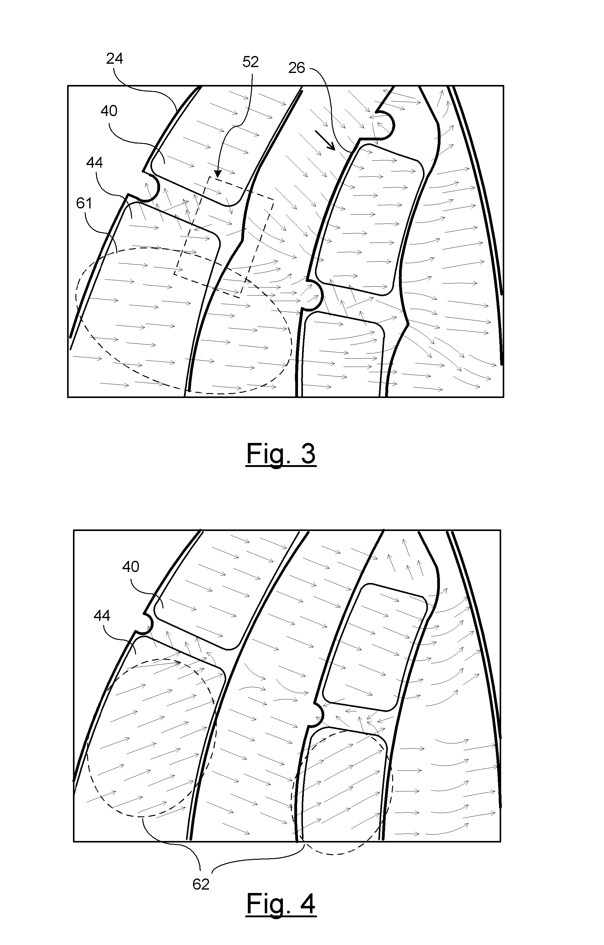
[0014]There is shown in FIG. 1 a section view of a permanent magnet motor 10. The permanent magnet motor 10 includes a rotor 12 coupled to a shaft 14. The rotor 12 can include any number of poles (e.g. 2, 4, 6, etc). The sectional view as shown illustrates one pole of the rotor 12 (e.g. north pole). A stator 16 is radially offset from the rotor 12 and is separated therefrom by a main air gap 18.

[0015]The function of the rotor 12 is to drive a component coupled to the shaft 14. The stator 16 when excited by an excitation voltage (e.g., 3-phase supply) generates a rotating magnetic field within the motor 10. The rotor, which functions as a permanent magnet locks in with the rotating magnetic field generated by the stator 16. The rotor 12 rotates along with the rotating magnetic field. When the rotator locks in with the rotating magnetic field, the motor 10 is in synchronization.

[0016]The rotor 12 as shown in FIG. 1 utilizes interior permanent magnets 20. It should be understood that t...


PUM


Abstract

A rotor for a permanent synchronous machine includes a rotor having a plurality of arcuately-shaped cavities formed within a rotor core structure. The plurality of arcuately-shaped cavities substantially concentrically layered with respect to an outer cylindrical wall of the rotor core structure. A plurality of permanent magnets is inserted within the plurality of arcuately-shaped cavities. Each cavity layer retains a permanent magnet of a first magnetic field strength disposed in end sections and a permanent magnet of a second magnetic field strength in a center section of each cavity layer. Each respective cavity includes an air barrier formed between the magnets having different magnetic field strengths. The air barrier generates a reluctance within an air barrier gap for directing a flow of flux generated by each third permanent magnet in a preceding layer in a direction toward each third permanent magnet in a succeeding layer.

Description

BACKGROUND OF INVENTION[0001]An embodiment relates generally to permanent magnet motors.[0002]A permanent magnet synchronous motor is an AC motor in which rotation rate of the shaft is synchronized with the frequency of the AC supply current. A rotating electric field is generated in the stator and the rotor follows the rotating electrical field of the stator. The rotor rotates in step with the field of the stator at a same rate. The rotor and the stator are said to be in synchronization.[0003]The permanent magnets used in conventional rotors are configured to provide a uniform field strength. Neodymium magnets, also known as rare earth magnets, are often desired due to their strong magnetic field strength which provides enhanced torque in motors. However, using rare earth magnets in a motor is costly and increases the overall price of the motor.SUMMARY OF INVENTION[0004]An advantage of an embodiment is the reduction in the content and weight of rare earth magnets which reduces the ...

Claims


Application Information

Patent Timeline
Patent Type & Authority Applications(United States)
IPC IPC(8): H02K1/27
CPCH02K1/2766
Inventor VYAS, RAJEEVNEHL, THOMAS WOLFGANGRAJALA, ALEXANDRU
Owner GM GLOBAL TECH OPERATIONS LLC
Why Eureka
Try Eureka