Switching regulator with integrated resonant circuit for ripple filtering

a technology of switching regulator and ripple filtering, which is applied in the direction of power conversion system, dc-dc conversion, instruments, etc., can solve the problems of difficult alignment of resonant notch with the fundamental frequency of ripple component, inevitably oscillating, and ripple component being particularly problemati

Active Publication Date: 2013-12-05
ANALOG DEVICES INC
View PDF3 Cites 16 Cited by
  • Summary
  • Abstract
  • Description
  • Claims
  • Application Information

AI Technical Summary

Benefits of technology

[0013]As noted above, the ripple component present in a switching regulator's output voltage is coherently related to the switching regulator clock, and has an associated fundamental frequency. The present switching voltage regulator and resonant circuit are arranged such that the resonant notch in the notch filter frequency response and the ripple component's fundamental frequency are matched. A resonant circuit theoretically provides infinite attenuation at its resonant frequency; in practice, when the resonant notch and the fundamental frequency of the ripple are matched, the resonant circuit provides far more ripple attenuation than does a low pass filter configuration. In addition, the inductor and capacitor making up the resonant circuit can act in concert with one or more decoupling capacitors coupled to the load to form a low pass filter which attenuates harmonics of the ripple's fundamental frequency.

Problems solved by technology

This increasing and decreasing inductor current is largely filtered by the regulator's storage capacitor, but some of this oscillation inevitably appears as a ripple component in the regulator's output voltage.
This ripple component can be particularly problematic when of the switching regulator's output voltage is driving an analog load, as the ripple frequencies typically get through the amplifier, ADC, etc. and corrupt the output.
As ripple is generally undesirable, many systems include circuitry designed to attenuate the ripple component.
A notch-type filter might also be considered; however, aligning the resonant notch with the fundamental frequency of the ripple component can be difficult.

Method used


Image

  • Switching regulator with integrated resonant circuit for ripple filtering
  • Switching regulator with integrated resonant circuit for ripple filtering
  • Switching regulator with integrated resonant circuit for ripple filtering

Examples


Embodiment Construction

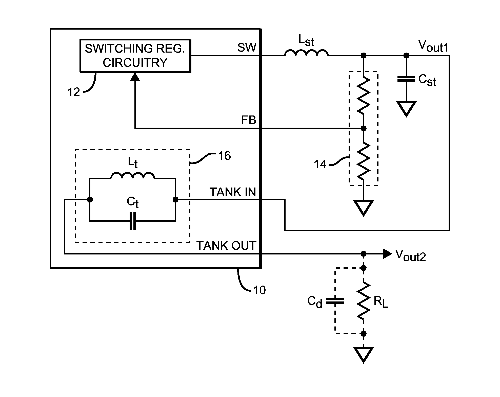
[0024]The present system is a switching regulator which includes an integrated resonant circuit designed to provide ripple filtering; a diagram illustrating the basic principles of the invention is shown in FIG. 1. An integrated circuit (IC) 10 contains:[0025]switching regulator circuitry 12 (which would typically include the regulator's switching transistor(s)) and be arranged to produce an output (at SW) which, when coupled to a storage inductor (Lst) and storage capacitor (Cst), form a switching voltage regulator which produces an output voltage (Vout1)when in use. A feedback signal (FB) which varies with Vout1 (provided by, for example, a voltage divider 14) is typically fed back to regulator circuitry 12 to enable Vout1 to be regulated. As noted above, the switching regulator operates at a switching frequency (fsw) which is derived from the frequency of the switching regulator's clock (which is typically generated internally but which might alternatively be provided externally)...


PUM


Abstract

A switching regulator IC contains both switching regulator circuitry and an inductor and a capacitor connected in parallel to form a resonant circuit having an associated notch filter frequency response arranged such that, when connected to receive the regulated output voltage, the resonant circuit attenuates the ripple component. This is accomplished by matching the resonant notch to the ripple's fundamental frequency, either manually or automatically. In addition, the resonant circuit's inductor and capacitor can act in concert with decoupling capacitors coupled to the load to form a low pass filter which attenuates harmonics of the ripple's fundamental frequency.

Description

BACKGROUND OF THE INVENTION[0001]1. Field of the Invention[0002]This invention relates generally to switching regulators, and more particularly to circuits designed to filter the ripple component of the regulator's output voltage.[0003]2. Description of the Related Art[0004]The operation of a switching regulator requires that one or more switching elements be switched on and off at a particular switching frequency, which causes the current in the regulator's storage inductor to increase and decrease at the switching frequency. This increasing and decreasing inductor current is largely filtered by the regulator's storage capacitor, but some of this oscillation inevitably appears as a ripple component in the regulator's output voltage.[0005]This ripple component can be particularly problematic when of the switching regulator's output voltage is driving an analog load, as the ripple frequencies typically get through the amplifier, ADC, etc. and corrupt the output. The ripple is not bro...

Claims


Application Information

Patent Timeline
Patent Type & Authority Applications(United States)
IPC IPC(8): G05F1/10
CPCG05F1/10H02M1/14H02M3/155
Inventor MEEHAN, PATRICK J.CONWAY, THOMASLIMJOCO, ALDRICKO'SULLIVAN, DONAL G.
Owner ANALOG DEVICES INC
Why Eureka
Try Eureka