Waveguide Antenna Having Annular Slots

a waveguide antenna and annular slot technology, applied in the field of telecommunications, can solve the problems of prohibitive antenna behaviour and limit the performance of antennas

Inactive Publication Date: 2013-12-05
ORANGE SA (FR)
View PDF13 Cites 11 Cited by
  • Summary
  • Abstract
  • Description
  • Claims
  • Application Information

AI Technical Summary

Benefits of technology

[0028]The presence of a second annular slot of which the central part includes the first annular slot makes it possible to obtain a dual-band antennal element. The ante

Problems solved by technology

This high level of cross-polarization limits the performance of antennas based on a guide with rectangular slots when used with a depoi

Method used


Image

  • Waveguide Antenna Having Annular Slots
  • Waveguide Antenna Having Annular Slots
  • Waveguide Antenna Having Annular Slots

Examples


Embodiment Construction

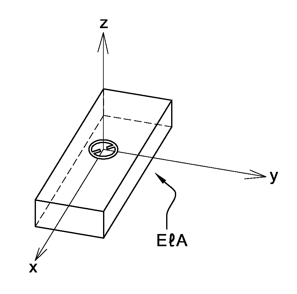
[0070]FIG. 3a is a diagram showing an embodiment of an antennal element E1A according to the invention. The antennal element E1A with a slotted guide according to the invention contains at least one conductive surface Fs provided with at least one annular slot Fan. Within the meaning of the invention an annular slot is a slot, which has the peculiarity of delimiting a conductive central region Zc and of electrically insulating it from the rest of the conductive upper surface Fs.

[0071]The annular slot is delimited by an inner edge and an outer edge separated by a distance d. The depth of the slot is at least that of the thickness of the metal layer of the upper surface Fs so as to electrically insulate the central region Zc from the rest of the surface Fs.

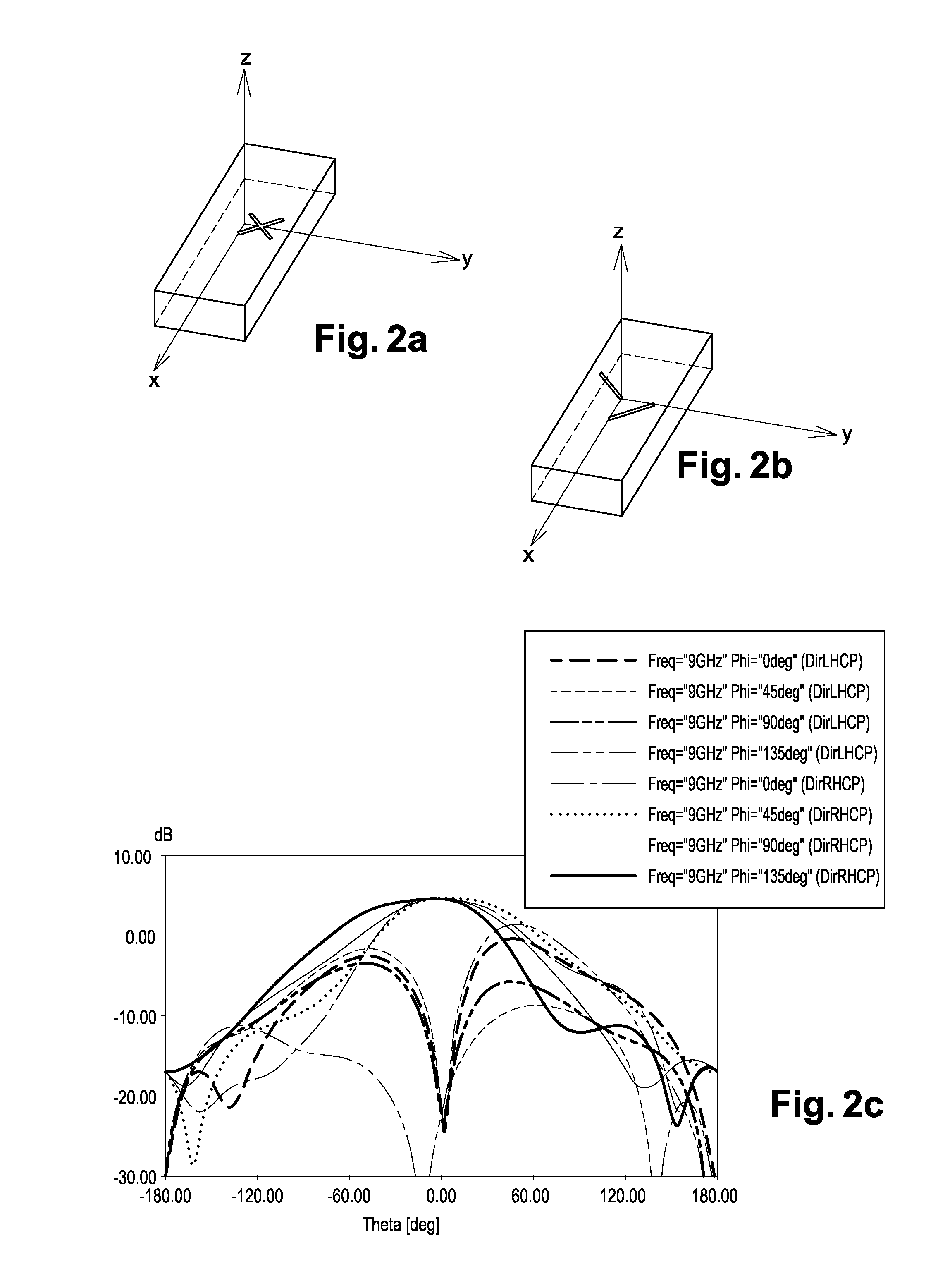
[0072]The curves in FIG. 3b show the elevational radiation of this antennal element corresponding to FIG. 3a for various planes offset by an angle of bearing Phi (0°, 45°, 90°, 135°) with respect to the axis of the guide. The diagra...


PUM


Abstract

A slotted waveguide antenna element s provided, which includes at least one conductive surface provided with at least one annular slot, which defines at the central portion thereof a conductive zone and which electrically insulates the zone from the rest of the surface.

Description

CROSS-REFERENCE TO RELATED APPLICATION[0001]This Application is a Section 371 National Stage Application of International Application No. PCT / FR2012 / 050311, filed Feb. 13, 2012, which is incorporated by reference in its entirety and published as WO 2012 / 107705 on Aug. 16, 2012, not in English.FIELD OF THE INVENTION[0002]The present invention relates to the field of telecommunications. Within this field, the invention relates more specifically to antennas intended to receive or transmit a telecommunications signal.[0003]The antenna can be used in a variety of systems. Its design based on the slotted guide technique allows it to be used in on-board systems, i.e. on a typically mobile medium such as a train or an aeroplane, for which the size, weight, and power consumption constraints can be extremely strict. The antenna is more specifically suitable for so-called “high-bit-rate” or even “very-high-bit-rate” connections, for example for satellite transmissions in the Ka band, which ext...

Claims


Application Information

Patent Timeline
IPC IPC(8): H01Q13/18
CPCH01Q13/18H01Q1/246H01Q13/106H01Q13/20H01Q21/0037H01Q21/0043H01Q21/068
Inventor RATAJCZAK, PHILIPPE
Owner ORANGE SA (FR)
Why Eureka
Try Eureka