Replacement vehicle lighting apparatus

a technology for replacing vehicles and lighting equipment, which is applied in the direction of lighting and heating equipment, semiconductor devices for light sources, transportation and packaging, etc., can solve the problems of deteriorating led lights themselves, or their surroundings, and generating a significant amount of heat in semiconductor junctions, so as to achieve convenient replacement of bulbs and reduce the luminous intensity of leds. , the effect of reducing the luminous intensity

Active Publication Date: 2022-11-15
PUTCO
View PDF21 Cites 0 Cited by
  • Summary
  • Abstract
  • Description
  • Claims
  • Application Information

AI Technical Summary

Benefits of technology

[0014]It is a further object, feature, and / or advantage of the present invention to replace original equipment and replacement standardized sealed beam units used in motor vehicle headlighting systems.
[0015]It is still yet a further object, feature, and / or advantage of the present invention to ensure the availability of replacement light sources provide equivalent performance and are thus interchangeable with original equipment light sources.
[0016]It is still yet a further object, feature, and / or advantage of the present invention to provide access for convenient replacement of the bulbs without special tools.
[0017]The replacement vehicle lighting apparatus disclosed herein can be used in a wide variety of applications. For example, the lighting apparatus can employ a wide variety of filaments, including LEDs that form part of a chip scale package (“CSP”). In some embodiments, the luminous intensity of these CSP LEDs can be limited while still providing the operator with the ability to clearly see objects external to the automobile at night. For example, preferred light outputs can be restricted such that the lighting apparatus emits no more than seventy five-thousand (75,000) candela, more preferably emits no more than fifty thousand (50,000) candela, and most preferably emits no more than (20,000 candela). The measure of the total quantity of visible light emitted by said CSP LEDs per unit of time can, in some embodiments, be characterized by a luminous flux of between one thousand and two thousand lumens (1000-2000 lm). In other embodiments, the total quantity of visible light emitted can reach as high as five thousand lumens (5000 lm).
[0018]Filaments can emit lights of colors other than the standard yellow or white color of a headlight / fog light. Filaments can also include sealants which alter the color of light emitted. Additionally, filaments can even be a light emitter of the type that can, in real-time, change the color of light emitted, such as red-green-blue light-emitting diodes (“RGB LEDs”).
[0019]It is preferred the apparatus be safe, cost effective, and durable. For example, the lighting apparatus should be substantially fireproof, adapted to dissipate static charges, and / or failure (e.g. cracking, crumbling, shearing, creeping) due to excessive pressure and / or prolonged exposure to tensile, compressive, and / or balanced forces acting on the lighting apparatus. The vehicle lighting apparatus can also include watertight seals, such as those that employ elastomeric gaskets, and other chemical sealants applied to various surfaces of the vehicle lighting apparatus to prevent moisture from seeping into the collar and / or components of the integrated circuit.

Problems solved by technology

Thus, it is no surprise these measures have provided inadequate to automobile operators, especially those who drive in heavily wooded areas.
High intensity LED lights, especially when used for headlights and fog lights can also generate a significant amount of heat in their semiconductor junctions.
This heat can cause problems such as melting or otherwise deteriorating the LED light itself, or its surroundings.
In extreme cases the heat can create a fire risk.
Fans are not ideal because they consume energy, take up valuable space, make noise, and tend to wear out before the LED lighting element.
Using a large rigid body to act as a heat sink is also problematic because of cost and space requirements.
However, the trend toward use of LED and HID bulbs is not without fault, and can even make roads less safe, if implemented poorly.
Other manufacturers implement wild beam patterns, colors, and intensities that together synergize to cause increased risk for distracting other drivers on the road.
The beams emitted form these products can reflect off of objects and cause significant glare.

Method used


Image

  • Replacement vehicle lighting apparatus
  • Replacement vehicle lighting apparatus
  • Replacement vehicle lighting apparatus

Examples


Embodiment Construction

[0057]The present disclosure is not to be limited to that described herein. Mechanical, electrical, chemical, procedural, and / or other changes can be made without departing from the spirit and scope of the present invention. No features shown or described are essential to permit basic operation of the present invention unless otherwise indicated.

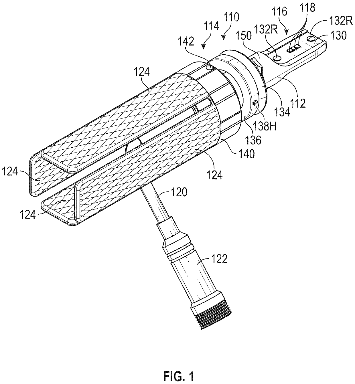
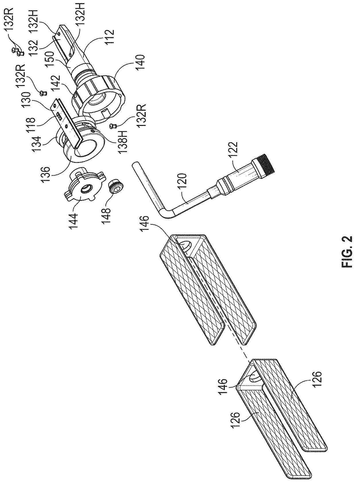
[0058]FIG. 1 and FIG. 2 show an LED lamp 110 according to one embodiment of the present invention. The LED lamp 110 is adapted for use as a headlight in an automobile. The LED lamp 110 includes a tower body 112 and mounting structure 114 that permit the lamp 110 to be mounted on an automobile. Together the tower body 112 and mounting structure 114 provide a mounting base that is adapted for mounting to a light fixture, such as an automobile headlight. The tower body 112 includes an opening and / or exposed portion 116 through which light emitting diodes 118 are provided. The tower body 112 may include features near the light emitting diode ope...


PUM


Abstract

A replacement lighting apparatus for automobiles is slim and includes an industry-leading footprint to fit into modern headlamps' minimal housing space. The lighting apparatus employs chip scale package light emitting diodes (CSP LEDs), flexible metal heat sinks, an improved collar having a watertight seal formed with an elastomeric gasket and the use of at least one, if not multiple, set screws, a wire harness with a nylon braided sleeve, and a solid-state design for maximum performance, long life, and superior scientifically proven heat mitigation.

Description

FIELD OF THE INVENTION[0001]The present invention relates generally to vehicle lights. More specifically, the invention relates to a replacement vehicle lighting apparatus that uses light emitting diodes (LEDs) as a filament, that when installed within the OEM headlamp housing of an automobile, can maintain pressure within a chamber of said headlamp during operation without causing significant damage or showing other unacceptable signs of wear to the replacement vehicle lighting apparatus and / or other components of the headlamp housing.BACKGROUND OF THE INVENTION[0002]The background description provided herein gives context for the present disclosure. Work of the presently named inventors, as well as aspects of the description that may not otherwise qualify as prior art at the time of filing, are neither expressly nor impliedly admitted as prior art.[0003]Incandescent light bulbs utilize a small thin wire with two bigger wires holding it up. The electron emitting element in a vacuum...

Claims


Application Information

Patent Timeline
Patent Type & Authority Patents(United States)
IPC IPC(8): B60Q1/00F21K9/232F21S45/50F21S45/47F21S41/141
CPCF21K9/232F21S41/141F21S45/47F21S45/50F21Y2115/10F21S41/148F21S41/192F21S45/00
Inventor SCHRAMM, CONNERFREEMAN, PARKERHOOGENDOORN, SETHNIEMEYER, NICHOLASADAIR, PAUL THOMASELWELL, JAMES P.
Owner PUTCO
Why Eureka
Try Eureka