Multi-step simplified optimal trajectory control (SOTC) based on only Vo and I load

a multi-step, optimized technology, applied in the direction of electric variable regulation, process and machine control, instruments, etc., can solve the problem that the control characteristics of the resonant converter are much more complex than those of the pwm converter

Active Publication Date: 2018-09-11
VIRGINIA TECH INTPROP INC
View PDF13 Cites 0 Cited by
  • Summary
  • Abstract
  • Description
  • Claims
  • Application Information

AI Technical Summary

Benefits of technology

[0005]In one embodiment, the present invention provides a multi-step simplified optimal trajectory control (SOTC) based on VO and ILoad to solve the challenges in the control of the resonant converter.
[0006]In other embodiments, the present invention provides a simple control scheme, and equivalent performance as an OTC, while at the same time the present invention can be easily extended to high frequency applications.

Problems solved by technology

However, the control characteristics of the resonant converters are much more complex compared to PWM converters due to the dynamics of the resonant tank.

Method used


Image

  • Multi-step simplified optimal trajectory control (SOTC) based on only Vo and I load
  • Multi-step simplified optimal trajectory control (SOTC) based on only Vo and I load
  • Multi-step simplified optimal trajectory control (SOTC) based on only Vo and I load

Examples


Embodiment Construction

[0053]Detailed embodiments of the present invention are disclosed herein; however, it is to be understood that the disclosed embodiments are merely exemplary of the invention, which may be embodied in various forms. Therefore, specific structural and functional details disclosed herein are not to be interpreted as limiting, but merely as a representative basis for teaching one skilled in the art to variously employ the present invention in virtually any appropriately detailed method, structure or system. Further, the terms and phrases used herein are not intended to be limiting, but rather to provide an understandable description of the invention.

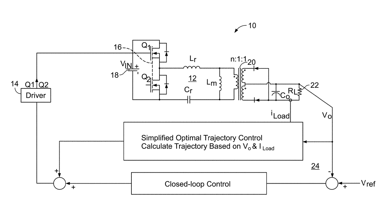
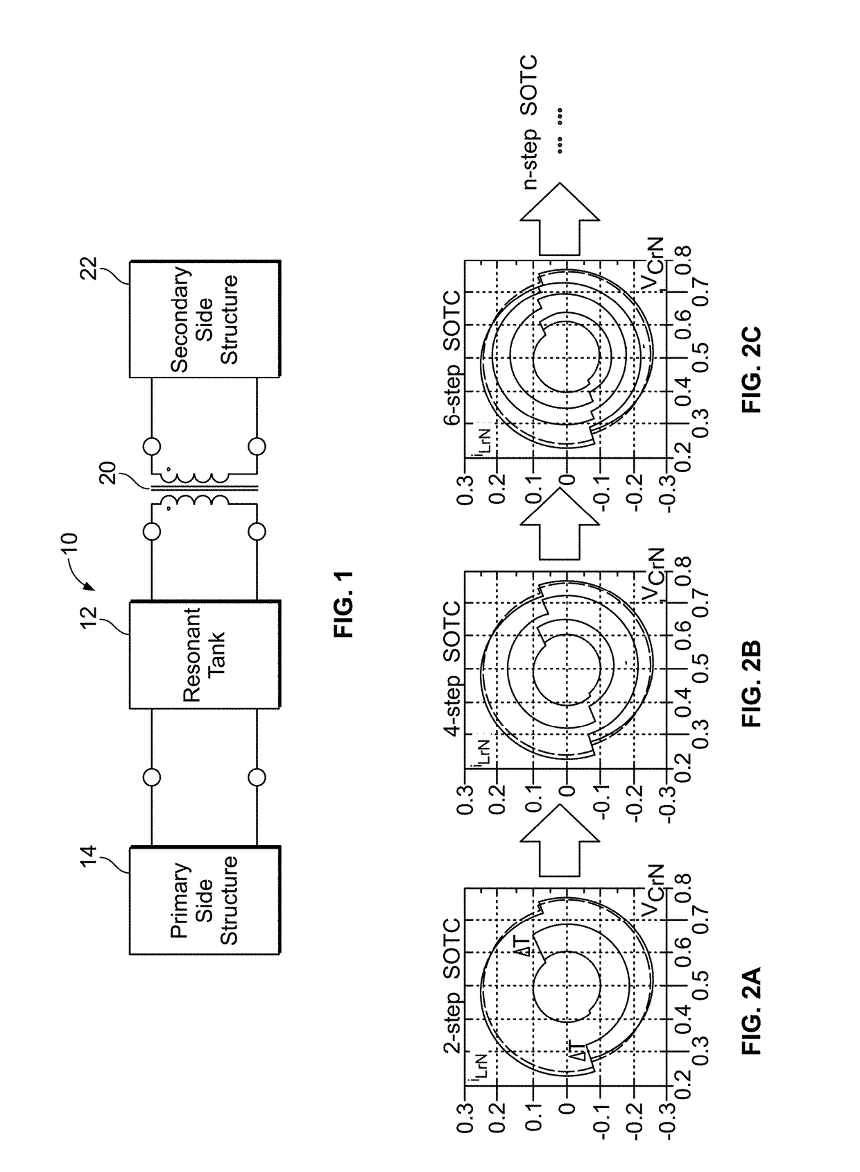
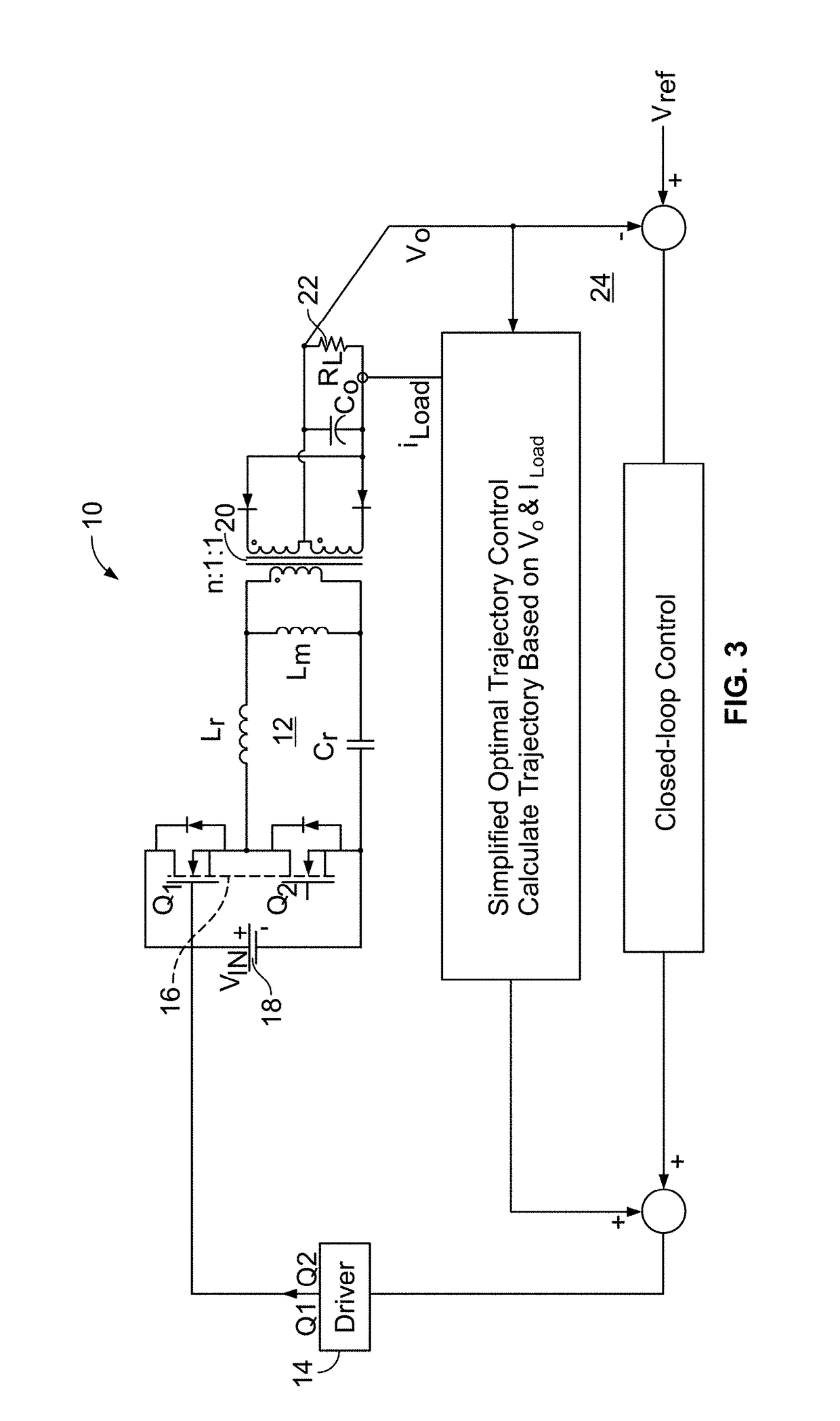
[0054]The structure of a basic resonant converter is shown in FIG. 1. It consists of primary side structure, resonant tank, transformer and secondary side structure. The control of resonant converter is a challenge due to the dynamics of the resonant tank.

[0055]In one embodiment, the present invention settles the resonant tank, which is mai...


PUM


Abstract

A resonant power converter is disclosed with a driving circuit generating a switching signal connecting power to a resonant tank circuit, with a voltage monitoring circuit measuring a voltage output and a load current. A micro-controller is operable with a control circuit for multiple step sampling with the switching signal at a switching frequency to settle the resonant circuit determined from the voltage output and load current. A fast load transient response at a high frequency with the resonant circuit provides the multiple step sampling to ensure enough time for micro-controller to calculate. Optimal trajectory control facilitates a burst mode of high frequency with the resonant circuit using adaptive multiple step sampling for an on-time to extend the burst operation range. A soft start-up process uses the micro-controller processing in multiple stages.

Description

RELATED APPLICATIONS[0001]This application claims the benefit of U.S. Provisional Application No. 62 / 142,128 filed Apr. 2, 2015 and herein incorporated by reference. This application also claims the benefit of U.S. Provisional Application No. 62 / 142,092 filed Apr. 2, 2015 and herein incorporated by reference.STATEMENT REGARDING FEDERALLY SPONSORED RESEARCH & DEVELOPMENT[0002]Not applicable.INCORPORATION BY REFERENCE OF MATERIAL SUBMITTED ON A COMPACT DISC[0003]Not applicable.BACKGROUND OF THE INVENTION[0004]The resonant converter, especially LLC resonant converters, have been widely used as a DC-DC converters due to its high efficiency and hold-up capability. However, the control characteristics of the resonant converters are much more complex compared to PWM converters due to the dynamics of the resonant tank. Optimal Trajectory Control (OTC) was first proposed to control Series Resonant Converter (SRC). Then state-trajectory analysis and control were employed to solve the challeng...

Claims


Application Information

Patent Timeline
Patent Type & Authority Patents(United States)
IPC IPC(8): H02M3/335H02M1/36H02M3/337H02M1/00
CPCH02M3/33546H02M3/3376H02M3/33515H02M3/33592H02M1/36Y02B70/16H02M2001/0058Y02B70/1433Y02B70/1475Y02B70/1491H02M2001/0035H02M1/0035H02M1/0058Y02B70/10
Inventor FEI, CHAOLEE, FRED C.FENG, WEIYILI, QIANG
Owner VIRGINIA TECH INTPROP INC
Why Eureka
Try Eureka