Display Brightness Adjustment

a brightness adjustment and display technology, applied in the field of display brightness adjustment, can solve the problems of high cost and balance, and achieve the effect of optimum balance, higher cost and better results

Active Publication Date: 2013-12-05
IBM CORP
View PDF6 Cites 13 Cited by
  • Summary
  • Abstract
  • Description
  • Claims
  • Application Information

AI Technical Summary

Benefits of technology

[0006]Preferably the array of light sensors extends around the display. In the preferred embodiment a bezel surrounding the screen is ringed with a circuit of light sensors. The denser the placement of these sensors, the better the results will be, but also the higher the cost so an optimum balance must be considered. When a shaft of light is cast across the screen, points on the bezel are detected where one light sensor has a higher reading than one of its neighbors. In the preferred embodiment the footprint of the shaft of light that is being cast across the screen is assumed to be a linear path between these points. The footprint is used to adjust the screen for optimal viewing: pixels in light areas can have their relative brightness raised (as pixels in the dark areas may equally have their brightness lowered). As such, the display quality across the whole screen is normalized.
[0007]More preferably the array of light sensors is a single circuit of light sensors one sensor thick. Other embodiments comprise: two circuits of light sensors; three circuits of light sensors; or more than three circuits of light sensors. The bezel surrounding the screen contains the light sensors circuit. The denser the placement of these sensors, the better the results will be, but the higher the cost so a balance must be considered. The preferred embodiment has only one sensor circuit for an effective low cost solution. Another embodiment uses two concentric circuits of sensors to eliminate some footprint errors. Another embodiment uses three concentric circuits of sensors so that curved footprints can be estimated.

Problems solved by technology

The denser the placement of these sensors, the better the results will be, but the higher the cost so a balance must be considered.

Method used


Image

  • Display Brightness Adjustment
  • Display Brightness Adjustment
  • Display Brightness Adjustment

Examples


Embodiment Construction

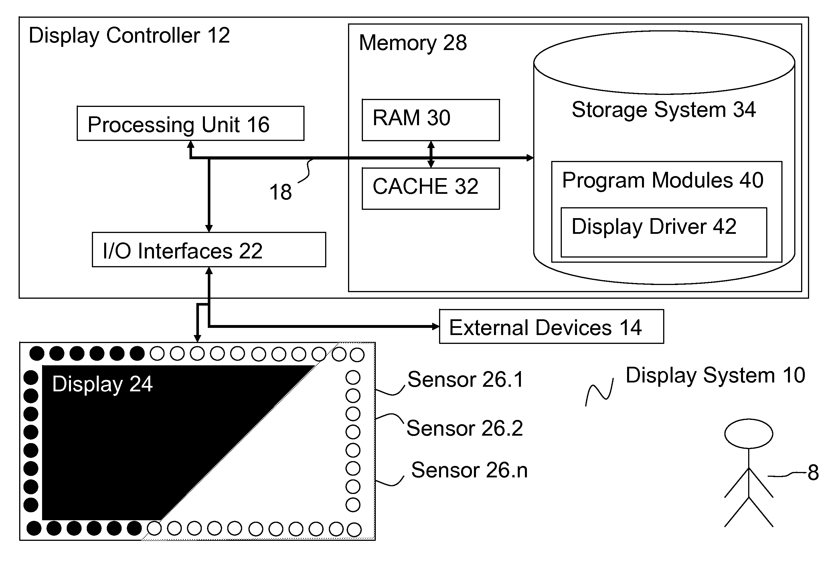
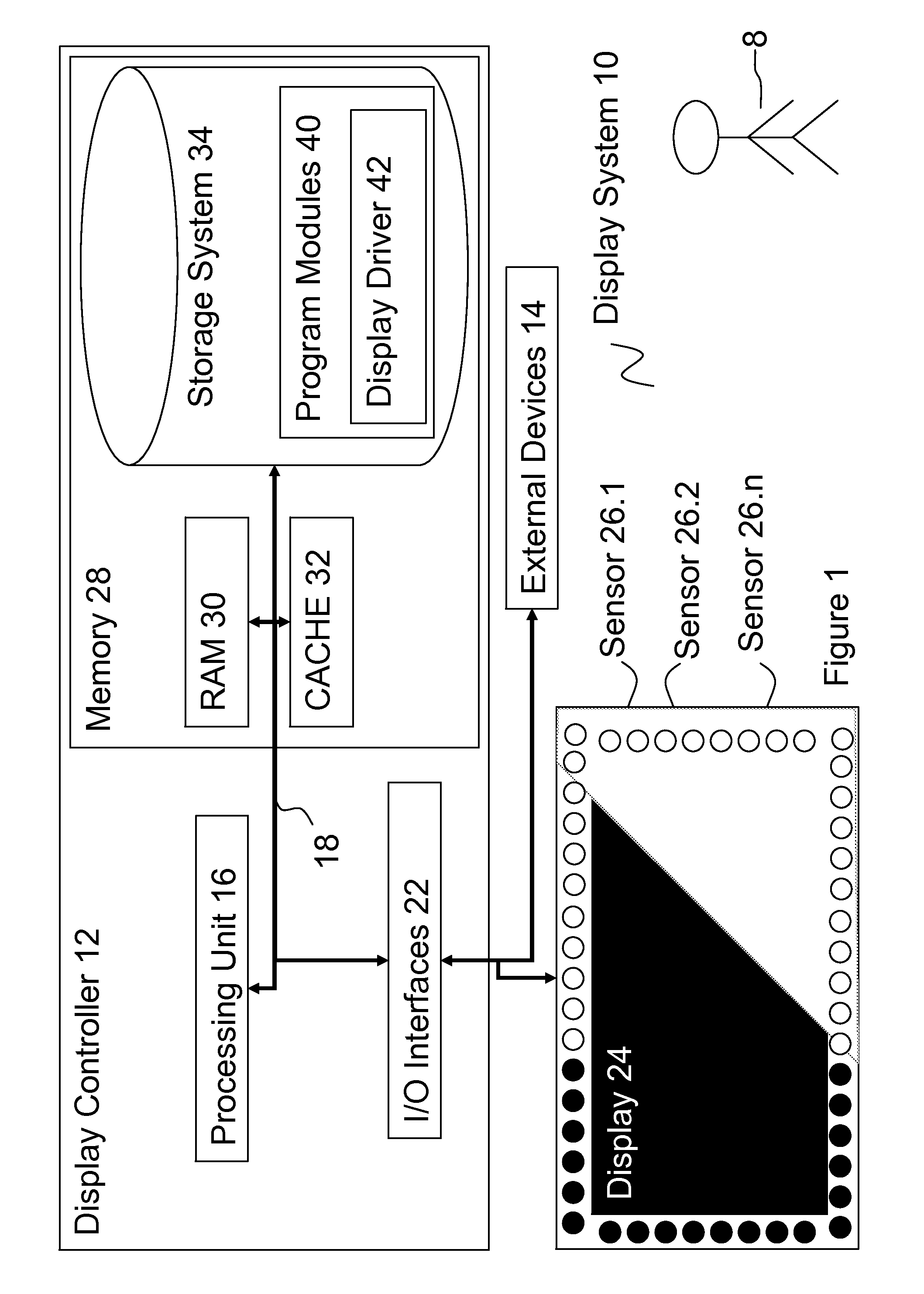
[0034]Referring to FIG. 1, there is shown a component diagram of a display system 10 according to the embodiments. Display system 10 is operational with numerous other general purpose or special purpose computing system environments or configurations. Examples of well-known computing processing systems, environments, and / or configurations that may be suitable for use with display system 10 include, but are not limited to, personal computer systems, server computer systems, thin clients, thick clients, hand-held or laptop devices, multiprocessor systems, microprocessor-based systems, set top boxes, programmable consumer electronics, network PCs, minicomputer systems, mainframe computer systems, and distributed cloud computing environments that include any of the above systems or devices or equivalents.

[0035]Display system 10 may be described in the general context of computer system-executable instructions, such as program modules, being executed by a computer system. Generally, prog...


PUM


Abstract

A display comprising an array of pixels having individually adjustable brightness levels; an array of light sensors fixed relative to the pixel array; and a brightness controller for estimating a glare footprint on the pixel array from light level data provided by the sensor array and for adjusting the relative brightness levels of pixels that fall in the estimated glare footprint.

Description

FIELD OF THE INVENTION[0001]This invention relates to a method and apparatus for display brightness adjustment.BACKGROUND[0002]The invention operates in the general environment of display brightness adjustment. When a shaft of light is cast across a screen, it can cause reduced viewing quality in an area whilst leaving other parts of the display unaffected. When viewing quality is important, a user will attempt to block out a light source casting glare or unwanted shafts of light onto screen. Normally darkening the environment works but this is not always possible.[0003]The effects of bright light on a screen can be attenuated by raising the brightness. Most devices with screens (for example, a television or a monitor) only allow the whole screen to be brightened or dimmed; adjusting to optimize affected areas can lead to the unaffected areas looking worse.[0004]A known solution automatically adjusts brightness by light-sensors built into a device. Mobile phones often make use of th...

Claims


Application Information

Patent Timeline
Patent Type & Authority Applications(United States)
IPC IPC(8): G09G3/32
CPCG09G3/3208G09G3/3225G09G2320/0233G09G2320/0285G09G2360/144G09G3/3406G09G2360/141G09G2380/10
Inventor MIRSKI-FITTON, ALEXANDER D. S.MOFFATT, EDWIN P. J.PILOT, RICHARD W.
Owner IBM CORP
Why Eureka
Try Eureka