
Method and User Equipment for Carrier Aggregation

a carrier and user equipment technology, applied in the field of wireless transmission techniques, can solve the problems of ineffective power consumption, lack of “reconfigurability”, and cost, and achieve the effect of convenient implementation

Active Publication Date: 2013-12-05
SEQUANS COMMUNICATIONS
View PDF6 Cites 21 Cited by
  • Summary
  • Abstract
  • Description
  • Claims
  • Application Information

AI Technical Summary

Benefits of technology

The proposed disclosure in this patent proposes a new way to efficiently use the processing capabilities of a network by granting processing power to each carrier based on its bandwidth. This results in a reduction of the number of digital converters and saves size and power consumption. In addition, this allows for a more flexible and practical approach to aggregating the analog signals of each carrier. Overall, this patent provides a more efficient and flexible way to process network traffic.

Problems solved by technology

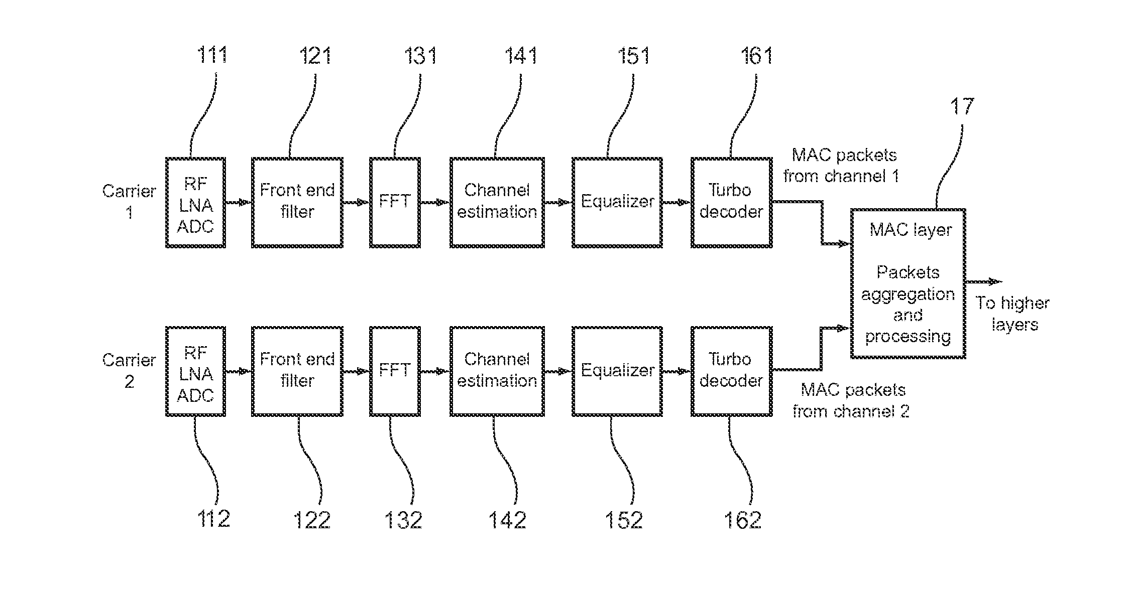
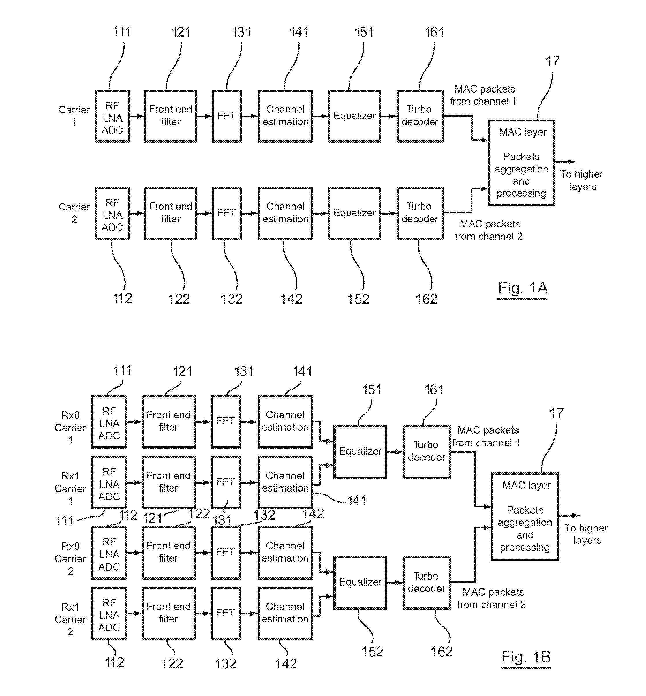
Thus a first disadvantage of the basic arrangement is its lack of “reconfigurability”.
Another disadvantage of the basic arrangement is its cost: to support all the scenarios as described above, each module shall be dimensioned to support the worst scenario per carrier.
Moreover, it appears also that managing independently each channels using several independent PHY layers, is not even efficient in terms of power consumption.
And in addition, the change of scenario leads to a new power consumption, which often involves great power consumption variations.
This results in saving of size and power consumption.

Method used


Image

  • Method and User Equipment for Carrier Aggregation
  • Method and User Equipment for Carrier Aggregation
  • Method and User Equipment for Carrier Aggregation

Examples


first embodiment

2. Description of a First Embodiment

[0088]The disclosure consists in a modified arrangement, which is depicted in the FIGS. 4A to FIG. 4C.

[0089]In particular, FIGS. 4A and 4B can be compared with prior art represented by FIGS. 1A to 1B as already commented.

[0090]Considering the example of FIG. 4A, the modified arrangement comprises a “front end” before the aggregation point (referring to the part of the chain of each channel that is upstream to the aggregation point) comprising two “front end” carrier processing chains, each “front end” carrier processing chain comprising only two modules. According to the example represented on FIG. 4A, only two carriers are aggregated, but it is possible that the disclosure provides as many “front end” carrier processing chain as the number of carriers to aggregate per receiving antenna.

[0091]Each “front end” carrier processing chain of modules comprises for example a first module (410 and 411) comprising a receiving antenna and radio frequency (R...

second embodiment

3. Description of a Second Embodiment and its Variants

[0118]In relation with FIG. 6A, a first variant of a second embodiment of the disclosure is represented.

[0119]Such a second embodiment consists in moving the aggregation point upstream in comparison with the first embodiment of FIG. 4A to 4C. More particularly according to the second embodiment of the disclosure, the aggregation point is moved inside the first module (410, 411) of each carrier processing chain of the first embodiment.

[0120]More precisely, the aggregation point (60) is moved before the analog to digital converter module ADC 6222, which performs the oversampling step.

[0121]Thus, the carriers are aggregated in the analog domain whereas they were aggregated in a digital domain according to the first embodiment. In comparison to the first embodiment, the first module (410, 411) is splitted in a radio frequency “front end” part (620, 621) comprising only a receiving antenna, a low-noise amplifier (LNA) and radio freque...


PUM


Abstract

User equipment is provided for receiving an OFDM signal. The user equipment includes a plurality of carrier processing chains and a carrier aggregation module, aggregating the signals received on each carrier processed by the plurality of carrier processing chains. The aggregation module delivers a set of aggregated signals of the plurality of carrier processing chains at the input of a Fast Fourier Transform module of a PHY layer processing subsystem of the user equipment. The Fast Fourier transform module is able to process a size of data according to a predetermined rate depending on the aggregated bandwidth of the set of aggregated signals of the plurality of carrier processing chains, and the carrier aggregation module includes at least one frequency shifter for frequency shifting carriers.

Description

CROSS-REFERENCE TO RELATED APPLICATIONS[0001]None.STATEMENT REGARDING FEDERALLY SPONSORED RESEARCH OR DEVELOPMENT[0002]None.THE NAMES OF PARTIES TO A JOINT RESEARCH AGREEMENT[0003]None.FIELD OF THE DISCLOSURE[0004]The disclosure relates to wireless transmission techniques.[0005]More specifically, the disclosure relates to a method for transmitting data in multi wireless technologies environment. Among wireless technologies, the most recently deployed are LTE (for “Long Term Evolution”) and WiMAX (for “Worldwide Interoperability for Microwave Access”).[0006]In particular, “Carrier aggregation” has been introduced in the release 10 of LTE in order to increase the throughput that a wireless mobile can experiment. The principle is that a User Equipment (UE) can transmit and receive on several wireless channels simultaneously instead of using a single channel.[0007]As several scenarios can be considered, the reconfiguration of the carrier aggregation modules involves a lot of changes.[00...

Claims


Application Information

Patent Timeline
IPC IPC(8): H04L27/26
CPCH04L27/2647H04L5/001
Inventor MUQUET, BERTRANDBRICENO, MAURICIO
Owner SEQUANS COMMUNICATIONS
Learn More