Percutaneous connection assembly for active medical devices

a technology of percutaneous connection and active medical devices, applied in the direction of electrotherapy, intravenous devices, light therapy, etc., can solve the problems of increasing the risk of therapy, limiting the life of batteries, and the need to use expensive embedded components,

Inactive Publication Date: 2013-12-05
SABIN PIERRE
View PDF7 Cites 0 Cited by
  • Summary
  • Abstract
  • Description
  • Claims
  • Application Information

AI Technical Summary

Problems solved by technology

This architecture is faced with two main drawbacks: battery life limitations and the need to use expensive embedded components.
This device replacement procedure adds additional procedure costs and device costs to the therapy, increases the risks of the therapy and lowers the quality of life of the patients.
Despite recent progress in battery cells and the advent of wirelessly rechargeable system

Method used


Image

  • Percutaneous connection assembly for active medical devices
  • Percutaneous connection assembly for active medical devices
  • Percutaneous connection assembly for active medical devices

Examples


first embodiment

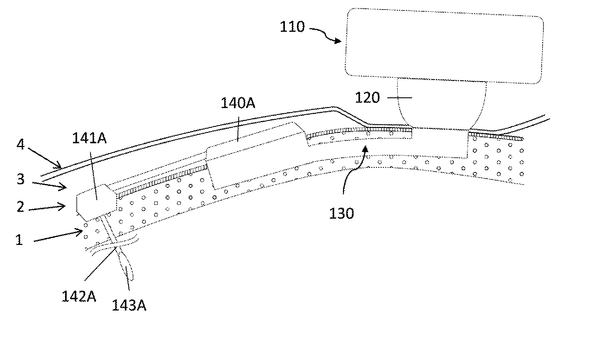
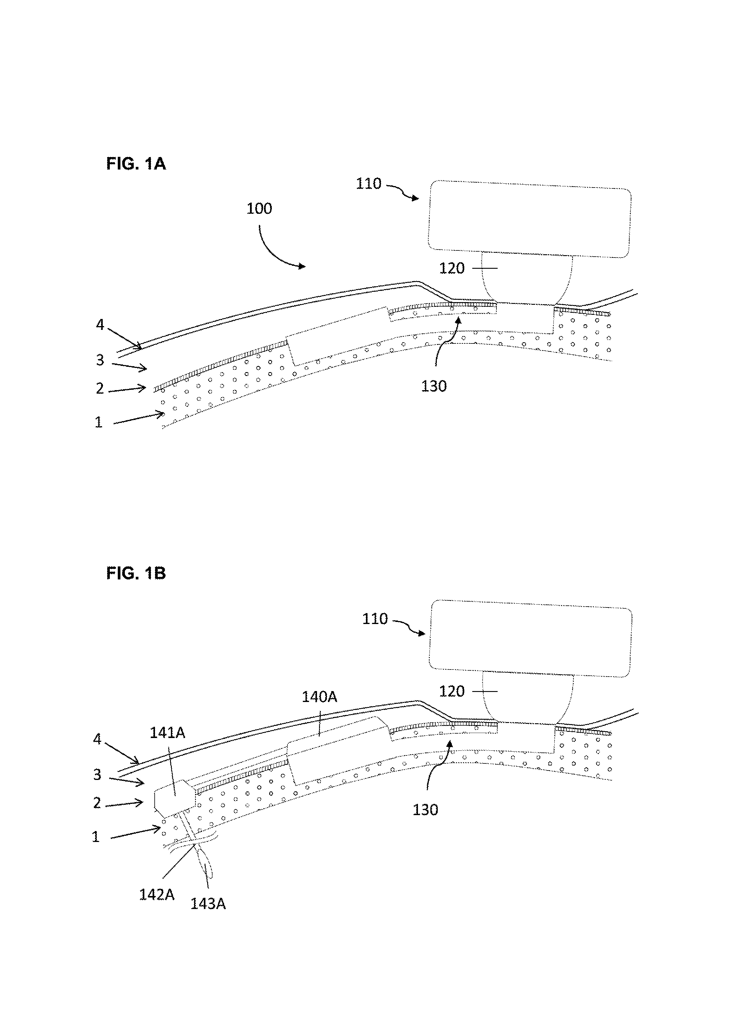
[0058]In a first embodiment the implant consists in a base and a tubular extension.

[0059]In order to secure bone anchorage the implant contains one or several anchoring means, that are designed for osseointegration of the implant in the osseous structure. At least three anchoring systems are considered:[0060]Cams; one or several cams are extending from the implant. The cams are activated through strips so that the external surface of the cams protrudes into the osseous structure wall maintaining therein the implant in position.[0061]Screws; plates are extending from the implant or alternatively independent plates are placed over the implant by the surgeon during the surgery. The plate has at least one through orifice intended to receive an osteosynthesis screw which are used for anchoring the implant in the osseous structure.[0062]Hooking system; the surface of implant is characterized by projections protruding relative to the surface of the osseous structure so that the implant can...

second embodiment

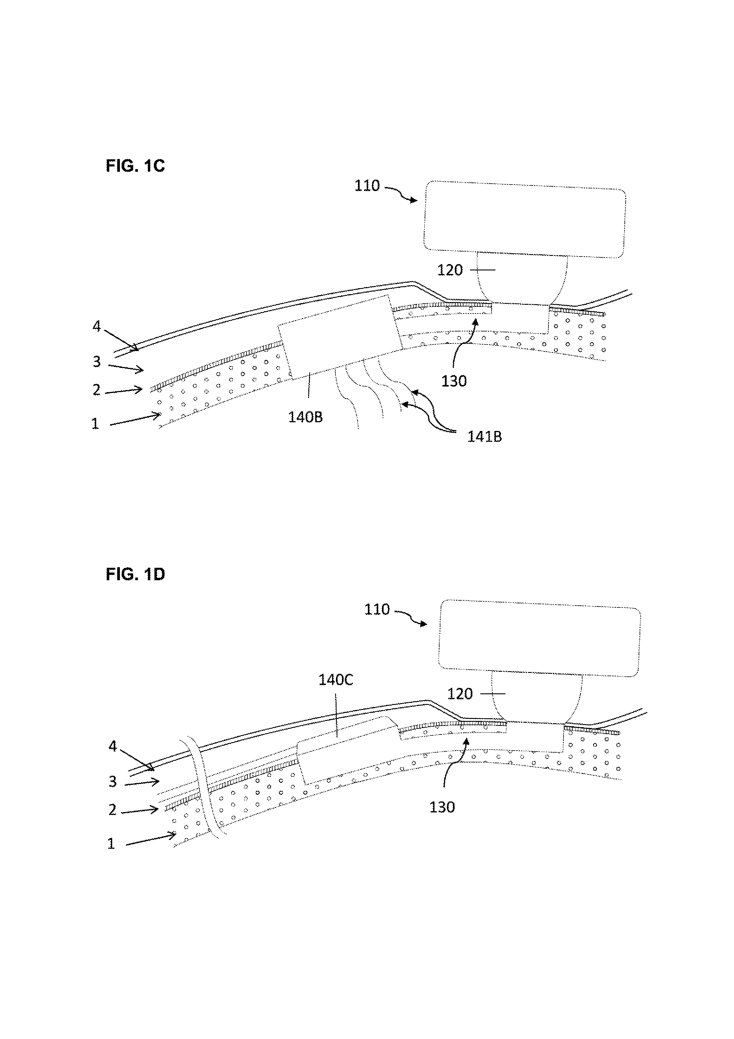
[0064]In a second embodiment the base and one or several tubular extension are not monobloc.

[0065]In this second embodiment, at least two anchoring means can be considered:[0066]A threaded system, wherein the base is threaded and preferably spherical shaped so that it can be screwed into the osseous structure.[0067]A hooking system, wherein the surface of the base is characterized by projections protruding relative to the surface of the osseous structure so that the implant can be impacted into the osseous structure.

[0068]The percutaneous system is designed to maintain mechanically the external elements and offer a percutaneous connection that is resistant from pathogens penetration. Therefore the implant geometry allow to anchor the implant in the osseous structure (1), to reduce the dermis (3) around the percutaneous passage so that the epithelium (4) can be sutured on the periosteum (2) forming an epithelial seal against pathogens. To lower the risk of adverse events the implant ...


PUM


Abstract

The invention concerns a novel medical system intended to be fixed in a surgically prepared osseous site of a patient and that connects external components to active entities located inside the body of the patient.
External components and active entities are designed to store, emit and/or transfer a specific flow, such as a flow of electricity, data, fluids, solids or light.
The external components can be housed in an external housing and bound to active entities being located within the body of the patient through connection elements located within a percutaneous abutment, an implant and possible additional implanted means of connections and/or stimulations.

Description

CROSS-REFERENCE TO RELATED APPLICATIONS[0001]This application claims the benefit of the filing date of U.S. Provisional Patent Application No. 61 / 653,304 filed May 30, 2012, the disclosure of which is hereby incorporated herein by reference.FIELD OF INVENTION[0002]The present invention relates to the implantation of medical devices in the body of an animal, in particular in the human body, especially the implantation of active medical devices, more particularly to set up an electric, liquid or optic connection between one or several external component to said body and one or several active elements implanted in said body.BACKGROUND OF THE INVENTION[0003]Active medical devices have expanded in multiple therapies spanning from cardiology to neurology and including urology as well as gastroenterology. The most common type of device is a fully-implanted electrical stimulator reckoning on an internal battery and embedded electronic components. This architecture is faced with two main dra...

Claims


Application Information

Patent Timeline
IPC IPC(8): A61N1/05A61N5/06A61M5/00
CPCA61N1/05A61M5/00A61N5/0613A61M39/0247A61M2039/0261A61M2039/0267A61N1/0529A61N2005/0627
Inventor SABIN, PIERRE
Owner SABIN PIERRE
Why Eureka
Try Eureka