Eureka AIR delivers breakthrough ideas for toughest innovation challenges, trusted by R&D personnel around the world.

Method for controlling interior permanent magnet synchronous motor

a permanent magnet synchronous motor and control method technology, applied in the direction of electric generator control, dynamo-electric converter control, dynamo-electric gear control, etc., can solve the problem of unstable torque control, linearity of output voltage (the maximum synthesized voltage) is broken, etc., to achieve the effect of improving fuel ratio and maximum output, reducing copper loss of the motor

Active Publication Date: 2013-12-12
HYUNDAI MOTOR CO LTD +2
View PDF6 Cites 14 Cited by
  • Summary
  • Abstract
  • Description
  • Claims
  • Application Information

AI Technical Summary

Benefits of technology

The invention allows for the use of a higher maximum voltage in a synchronous motor, even in low magnetic flux. This reduces copper loss and improves the fuel ratios and maximum output of hybrid and electric vehicles.

Problems solved by technology

where the linear voltage synthesis is enabled for the purpose of stable current control, there are several problems when as follows.
Second, since the inverter cannot generate a precise voltage when the maximum synthesized voltage is greater than the maximum voltage
in the voltage limiting circle (the area inside the circle) and deviates from the inscribed circle of the hexagon (the circular area) during the voltage modulation, the linearity of the output voltage (the maximum synthesized voltage) is broken and unstable torque control arises.
Thus, it is difficult to control a synchronous motor stably while operating the motor at high speeds.

Method used


Image

  • Method for controlling interior permanent magnet synchronous motor
  • Method for controlling interior permanent magnet synchronous motor
  • Method for controlling interior permanent magnet synchronous motor

Examples


Embodiment Construction

[0025]Hereinafter reference will now be made in detail to various embodiments of the present invention, examples of which are illustrated in the accompanying drawings and described below. While the invention will be described in conjunction with exemplary embodiments, it will be understood that present description is not intended to limit the invention to those exemplary embodiments. On the contrary, the invention is intended to cover not only the exemplary embodiments, but also various alternatives, modifications, equivalents and other embodiments, which may be included within the spirit and scope of the invention as defined by the appended claims.

[0026]It is understood that the term “vehicle” or “vehicular” or other similar term as used herein is inclusive of motor vehicles in general such as passenger vehicles including sports utility vehicles (SUV), buses, trucks, various commercial vehicles, watercraft including a variety of boats and ships, aircraft, and the like, and includes...


PUM


Abstract

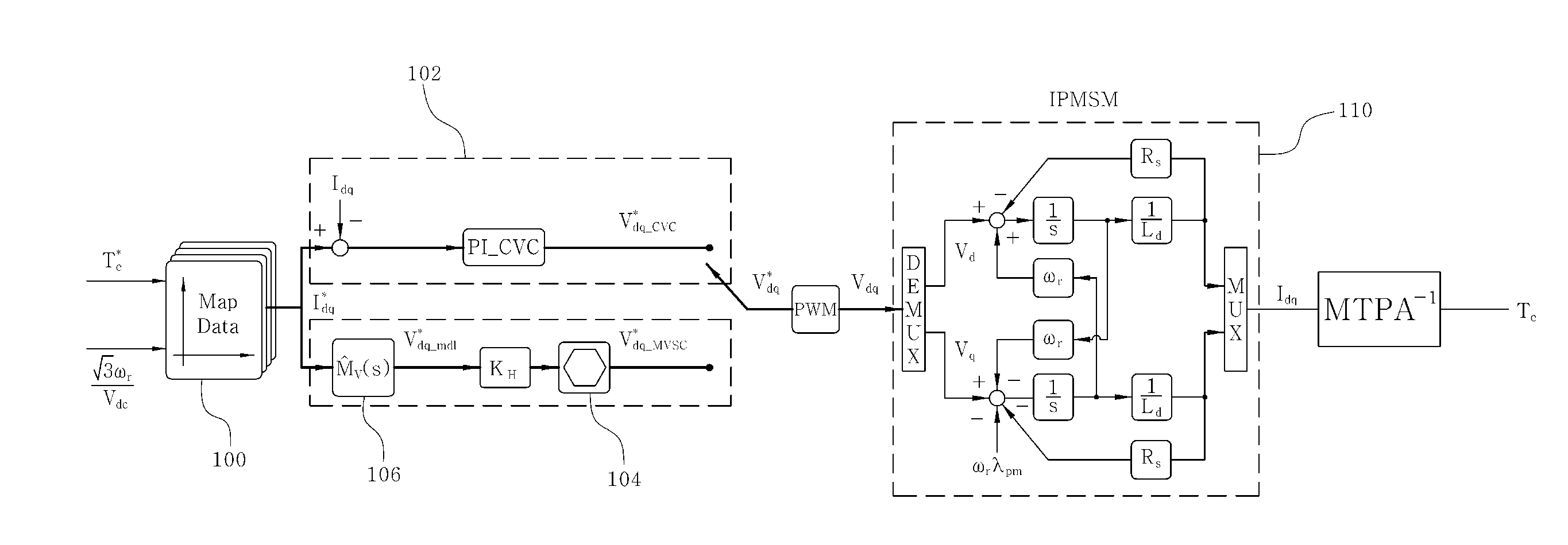
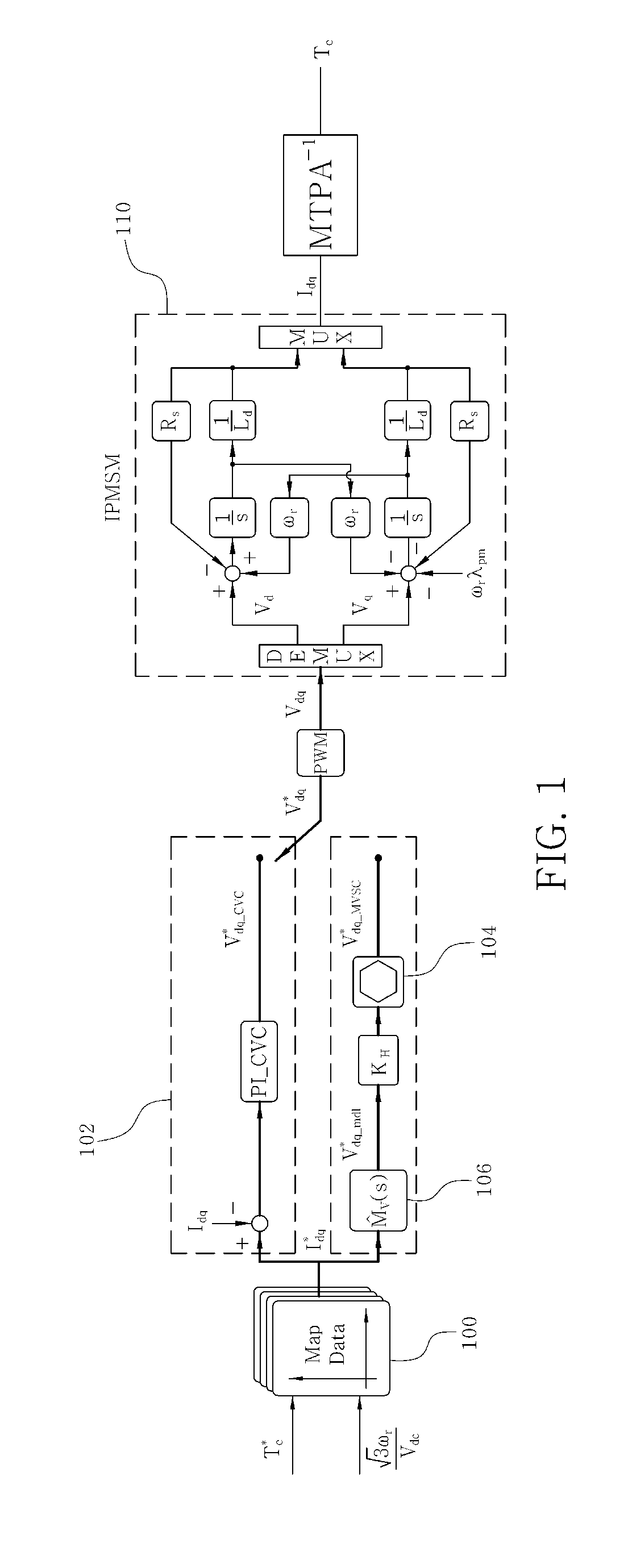
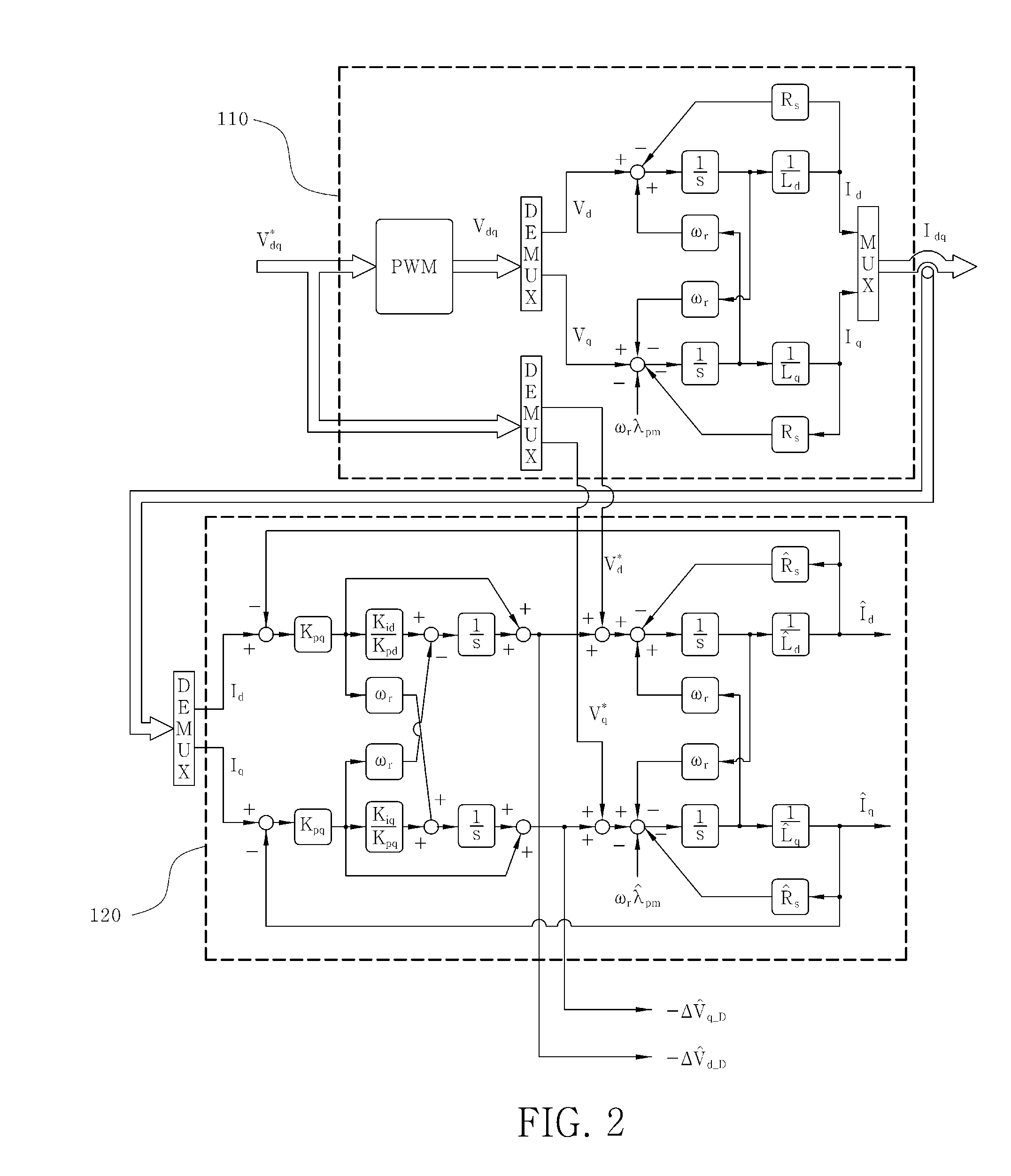
Disclosed is a method for controlling a permanent magnet synchronous motor to maximize use of voltages of a battery by voltage phase control within weak magnetic flux area and to achieve compensation for a torque error through a torque compensator when driving the permanent magnet synchronous motor for hybrid vehicles. In particular, the method controls a permanent magnet synchronous motor so that voltage use can be maximized in a weak magnetic flux area by using voltage near maximum voltage through voltage phase control utilizing magnetic flux-based map data receiving a torque command and motor speed / batter output voltage as inputs and torque error can be compensated using a torque compensation filter when a motor constant is changed in the weak magnetic flux by a circumstance parameter, when the permanent magnet synchronous motor mounted in a hybrid vehicle and an electric vehicle is driven.

Description

CROSS-REFERENCE TO RELATED APPLICATION[0001]This application claims under 35 U.S.C. §119(a) the benefit of Korean Patent Application No. 10-2012-0062625 filed Jun. 12, 2012, the entire contents of which are incorporated herein by reference.BACKGROUND[0002]1. Field of the Invention[0003]The present invention relates to a system and method of controlling a permanent magnet synchronous motor, and more particularly to a system and method of controlling a permanent magnet synchronous motor to maximize use of voltage created by a battery via voltage phase control within a weak magnetic flux area and to achieve compensation for a torque error through a torque compensator when driving the permanent magnet synchronous motor for a hybrid vehicle.[0004]2. Description of the Related Art[0005]In general, an interior permanent magnet synchronous motor (IPMSM) is a type of synchronous motor in which a permanent magnet inside the rotor core. IPMSMs are often used for industrial purposes or in hybri...

Claims


Application Information

Patent Timeline
IPC IPC(8): H02P21/00H02P21/22H02P23/16H02P27/04H02P27/08H02P29/00
CPCH02P21/0085H02P21/0089B60W10/08B60W20/00H02P21/14
Inventor BAE, SU HYUNKIM, SUNG KYUCHOI, WON KYOUNGKWAK, MU SHINSEOK, JUL KIKIM, SE HWAN
Owner HYUNDAI MOTOR CO LTD
Why Eureka
Eureka Blog
Learn More