Image processing apparatus and image processing method

a technology of image processing and image processing, which is applied in the field of image processing apparatus and image processing method, can solve the problems of large calculation amount (processing load) of this positioning process and process also requires a large calculation amount (processing load), and achieve the effect of waiting tim

Inactive Publication Date: 2013-12-12
CANON KK
View PDF2 Cites 64 Cited by
  • Summary
  • Abstract
  • Description
  • Claims
  • Application Information

AI Technical Summary

Benefits of technology

[0011]In the present invention, it is possible to predict the region for which the user desires refocus display, and to start or complete the refocus calculation before the user performs an operation of designating a region for refocus display. Accordingly, waiting time from the designation of refocus region by the user to display of a refocus image can be reduced.

Problems solved by technology

The calculation amount (processing load) of this positioning process is large.
In the case of blurring process, in particular, uniform burring of regions other than the focus region is not sufficient, but visually-natural blurring (for example, generation of captured image data with a shallow depth of field) needs to be achieved.
This process also requires a large calculation amount (processing load).

Method used


Image

  • Image processing apparatus and image processing method
  • Image processing apparatus and image processing method
  • Image processing apparatus and image processing method

Examples


embodiment 1

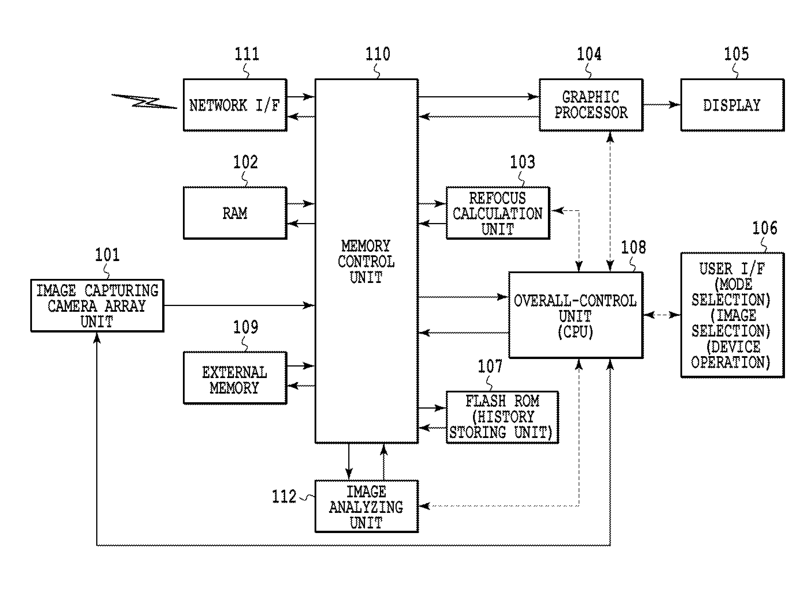
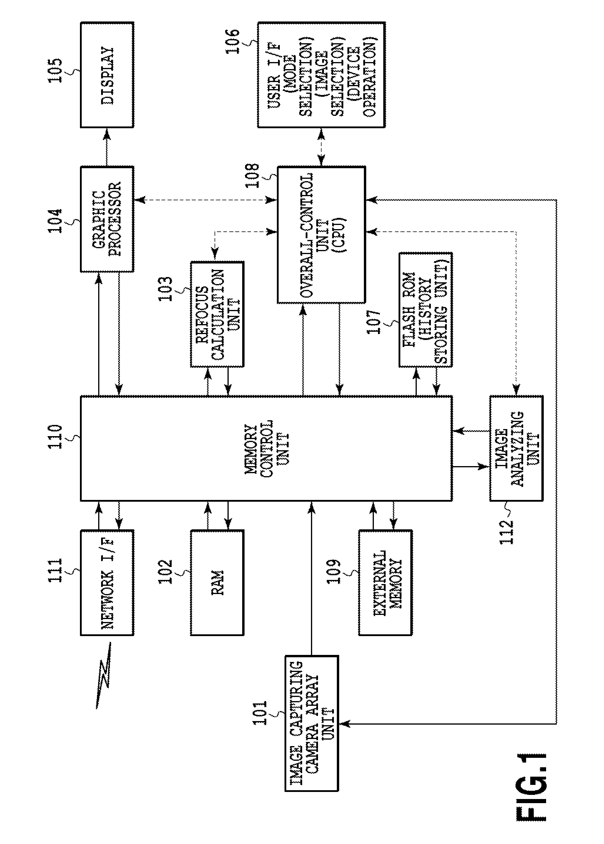
[0086]FIG. 1 is a block diagram showing an example of a hardware configuration of an image processing apparatus in Embodiment 1 of the present invention. FIG. 1 is described below in detail. An image capturing camera array (as known as camera array system, multiple lens camera and the like) unit 101 is an assembly of independent multiple cameras having independent optical systems and independent image capturing elements. The image capturing camera array unit 101 includes a controller of the image capturing elements and the like, and outputs a set of output data obtained from the multiple image capturing elements as multi-viewpoint image data.

[0087]A RAM 102 is a memory used to temporarily store the multi-viewpoint image data captured by the image capturing camera array unit 101, generated refocus image data, and other data in the middle of calculation. A Flash ROM 107 is a non-volatile memory and functions as a history information storage unit which accumulates and stores operation ...

embodiment 2

[0148]In Embodiment 2, description is given of an example in which a current reproduction refocus mode and history information on the reproduction refocus mode are added to prediction factors.

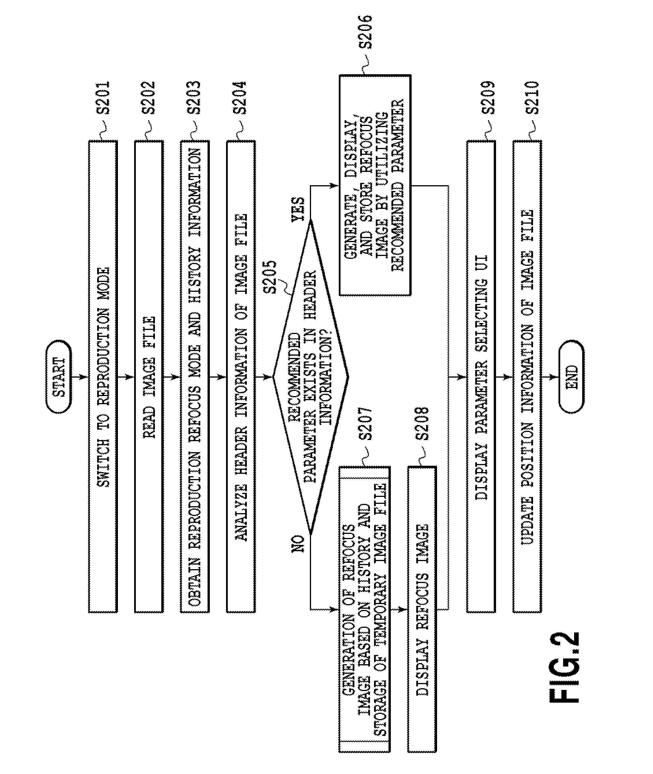
[0149]The description of step S207 of FIG. 2 (Embodiment 1) explains the process which is performed in a case where no recommended parameter exists in the image file stored in the memory, i.e. in the case where the display in the reproduction mode is performed for the first time. Moreover, the description related to step S207 of Embodiment 1 explains that the refocus calculation can be performed by predicting the refocus region on the basis of the past history information related to the reproduction of the refocus image.

[0150]Embodiment 2 is different from Embodiment 1 in that information on the current reproduction refocus mode and the history information on the current reproduction refocus mode are added to the prediction factor (i.e. past history information) of the refocus region shown in s...

embodiment 3

[0192]In Embodiments 1 and 2, there are shown examples of a case where attention is given to a target to be in focus (hereafter, referred to as focus target) in the generation of the refocus image. However, in some cases, a user can express his / her intention better if the attention is given to a target to be out of focus (hereafter referred to as non-focus target) in the generation of the refocus image.

[0193]In a currently-available image processing apparatus, in a case where a piece of refocus image data is generated at the time of image display, there no method of easily designating a portion desired to be set to a non-focus state. For example, the technique of Japanese Patent Laid-Open No. 2011-22796 described above is a technique of bringing multiple objects in focus by deep focus in a case where there are multiple objects. However, in a case where a specific object among the multiple objects in focus is desired to be brought out of focus, it is impossible to appropriately desig...


PUM


Abstract

In the case of a conventional image apparatus that generates refocus image on the occasion of image display, there is a waiting time because the image apparatus generates the refocus image in response to an operation of a user and requires the time to generate the refocus image. To address this situation, an image apparatus determines ranks of targets to be in focus based on history information indicating operation history, and generates sequentially combined image data from multi-viewpoint image data obtained by capturing images from multiple viewpoints, by focusing on the targets in accordance with the determined ranks.

Description

BACKGROUND OF THE INVENTION[0001]1. Field of the Invention[0002]The present invention relates to an image processing apparatus and an image processing method for processing image data on the basis of information obtained from multiple viewpoints.[0003]2. Description of the Related Art[0004]Currently, a method of displaying and checking a captured image in a so-called reproduction mode is known as a method of checking the captured image in an image capturing apparatus after image capturing.[0005]Moreover, an image capturing apparatus using a technique called “Light Field Photography” has been recently proposed (for example, R. Ng, M. Levoy, M. Brédif, G. Duval, M. Horowitz, P. Hanrahan: “Light Field Photography with a Hand-Held Plenoptic Camera”, Stanford Tech Report CTSR 2005-02 (2005), and Japanese Patent Laid-Open No. 2010-183316). The image capturing apparatus includes an image capturing lens, a microlens array, an image capturing element, and an image processing unit. Captured i...

Claims


Application Information

Patent Timeline
Patent Type & Authority Applications(United States)
IPC IPC(8): H04N5/232
CPCH04N5/23293H04N5/23212H04N5/23206H04N23/661H04N23/676H04N23/675H04N23/61H04N23/631H04N23/635
Inventor HAMANAKA, AKIYOSHIMASAKI, JUNYANAGASAKI, KATSUHIKOKOBAYASHI, MASAAKIFUKUI, TOSHIYUKIOYAMA, TOHRU
Owner CANON KK
Why Eureka
Try Eureka