
Electromagnetic interference emission suppressor

a technology of electromagnetic interference and suppressor, which is applied in the direction of power conversion systems, electric variable regulation, instruments, etc., can solve the problems of increasing the production of higher-order harmonics or electromagnetic interference (emi), increasing the size of magnetic components in power supplies, and increasing the weight, size and cost of power supplies., so as to reduce emi emissions, reduce ripple on the load, and minimize emi emissions

Active Publication Date: 2013-12-12
POWER SYST TECH
View PDF8 Cites 6 Cited by
  • Summary
  • Abstract
  • Description
  • Claims
  • Application Information

AI Technical Summary

Benefits of technology

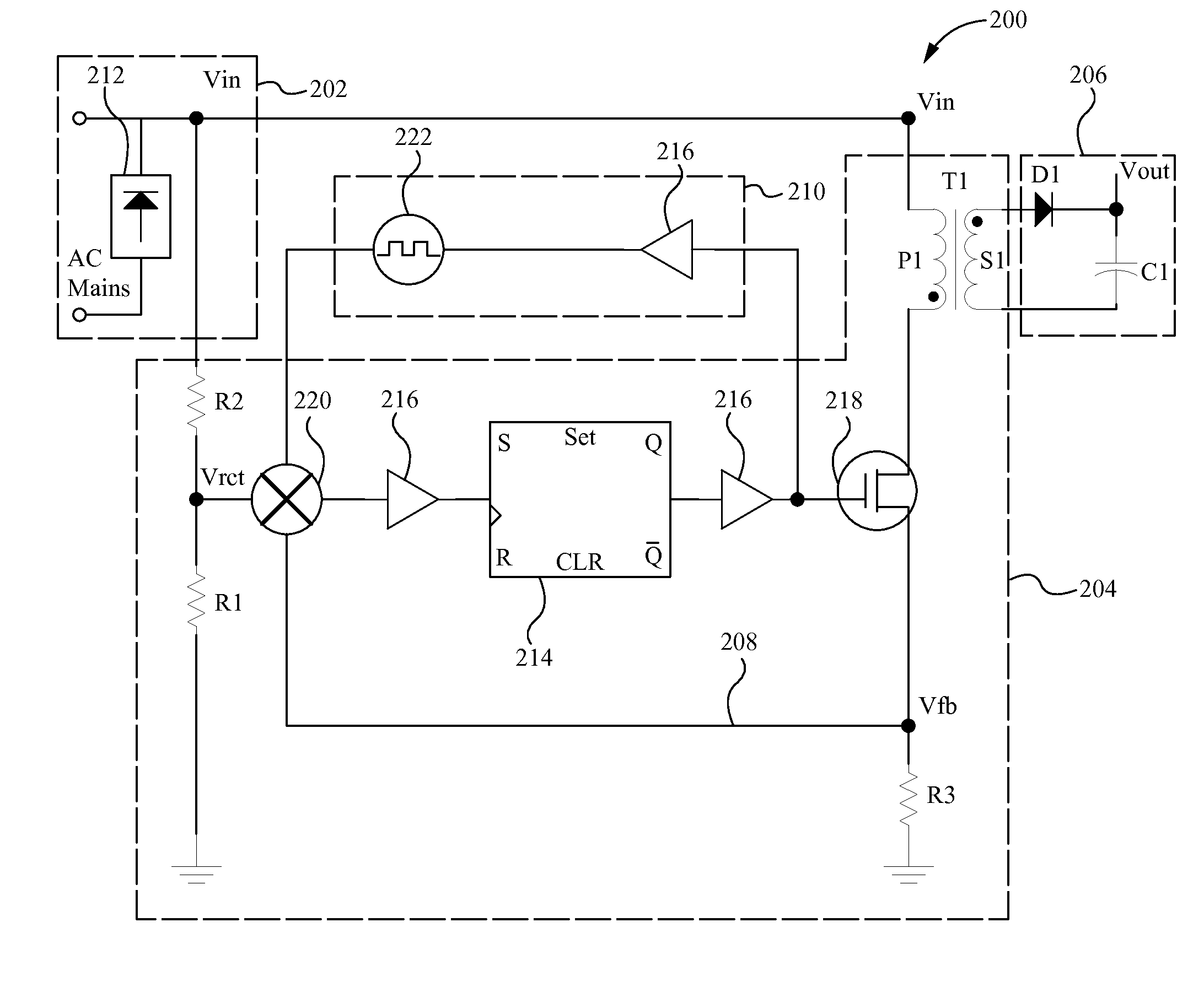
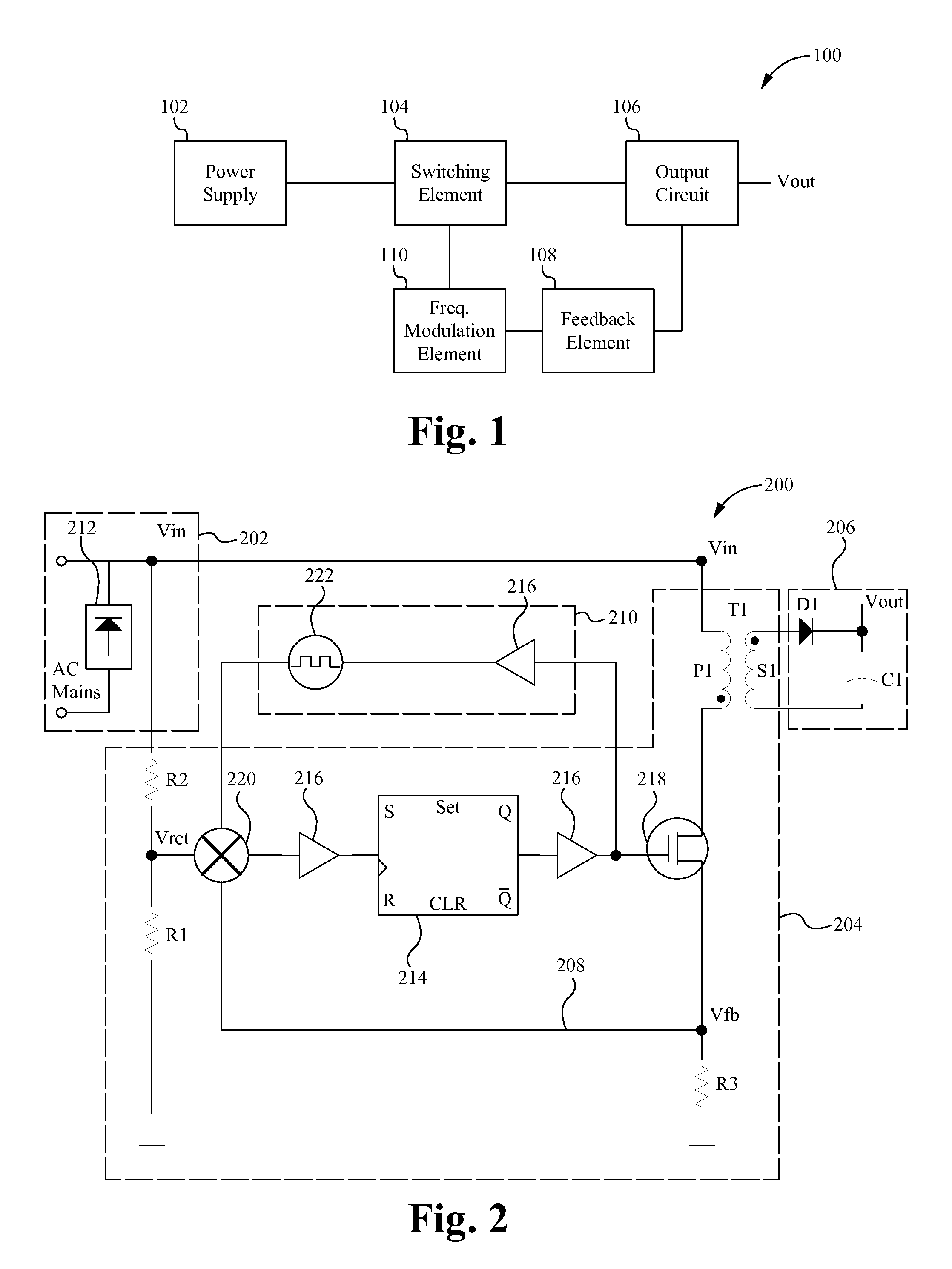
The patent describes a system that reduces emissions of electromagnetic interference (EMI) while minimizing ripple on the load. It achieves this by using a frequency modulation element that modulates the frequency of a switching element when it is drawing power from the main power supply. When the switching element is not drawing power, the frequency modulation element discontinues modulation to reduce ripple on the load. Overall, the system effectively minimizes EMI emissions on the main power supply and provides a smooth load.

Problems solved by technology

The disadvantage of operating at higher frequencies is the increased production of higher order harmonics or electromagnetic interference (EMI).
This approach has the disadvantage of increasing the size of magnetic components in a power supply.
This second approach has the disadvantage of adding to the weight, size and cost of power supplies.
The snubber circuit although effective in reducing EMI, compromises efficiency of a power converter.
Injecting noise into the gate drive of the converter has the disadvantage of distorting the output voltage signal.
Further, injecting noise directly into a gate drive only applies jitter to the rising and falling edges of the converter switching signal.
Moreover, because the jitter is continuous throughout the cycles of the switching signal, is outside the bandwidth of the amplifier and is injected outside the regulation loop of the switching circuit, it causes unwanted high ripple on the output of the switching circuit.
Accordingly, by continuously injecting jitter directly into the gate drive circuit, conventional power converters inhibit the efficiency of feedback loop and other features including zero voltage switching and sampling of the switching signal.

Method used


Image

  • Electromagnetic interference emission suppressor
  • Electromagnetic interference emission suppressor

Examples


Embodiment Construction

[0009]Embodiments of the present application are directed to an EMI emission suppressing system, device and method. Those of ordinary skill in the art will realize that the following detailed description of the EMI emission suppressing system, device and method is illustrative only and is not intended to be in any way limiting. Other embodiments of the EMI emission suppressing system, device and method will readily suggest themselves to such skilled persons having the benefit of this disclosure.

[0010]Reference will now be made in detail to implementations of the EMI emission suppressing system, device and method as illustrated in the accompanying drawings. The same reference indicators will be used throughout the drawings and the following detailed description to refer to the same or like parts. In the interest of clarity, not all of the routine features of the implementations described herein are shown and described. It will, of course, be appreciated that in the development of any...


PUM


Abstract

An EMI emission suppressing system, apparatus and method that enables the EMI produced by high frequency switching of a switching circuit to be suppressed via the transfer of the higher order harmonic emissions to a frequency range below the standard EMI bandwidth of less than 150 KHz by applying low frequency modulation or jitter into the feedback of a switching signal of the switching circuit. The EMI suppression is achieved with minimal added ripple on the output signal of the switching circuit by using discontinuous modulations in the form of only applying the low frequency modulation when the switch or higher order harmonic producing element of the switching circuit is accessing, or drawing power from, the main power supply.

Description

RELATED APPLICATIONS[0001]This Patent Application claims priority under 35 U.S.C. 119 (e) of the co-pending U.S. provisional application, Ser. No. 61 / 658,245, filed, Jun. 11, 2012, and entitled “Electromagnetic Interference Emission Suppressor”. This application incorporates U.S. provisional application, serial number in its entirety by reference.FIELD OF THE INVENTION[0002]The present invention relates to the field of power supplies. More particularly, the present invention relates to a power converter system with modulated control.BACKGROUND[0003]Every electrical device that connects with a power supply main is required not to pollute or transmit high frequency noise onto the main. The amount of electrical emission allowed by electrical devices is heavily regulated by the Federal Communications Commission (FCC). Conventional power supply designs have migrated to using higher operating frequencies since the higher operating frequencies allow a reduction in size of power supply comp...

Claims


Application Information

Patent Timeline
IPC IPC(8): H02M1/12H02M3/335
CPCH02M1/4258Y02B70/126H02M3/33507H02M1/12Y02B70/10
Inventor TELEFUS, MARK
Owner POWER SYST TECH
Learn More