Hydraulic control system having accumulator

a technology of hydraulic control system and accumulator, which is applied in the direction of positive displacement liquid engine, pump, machine/engine, etc., can solve the problems of hydraulic fluid not being delivered to the lubrication spot through the regulator valve, loss of hydraulic pressure, etc., to achieve the effect of reducing power loss, increasing flow volume, and simplifying the structure of hydraulic control system

Inactive Publication Date: 2013-12-12
TOYOTA JIDOSHA KK
View PDF5 Cites 9 Cited by
  • Summary
  • Abstract
  • Description
  • Claims
  • Application Information

AI Technical Summary

Benefits of technology

[0018]The hydraulic control system of the present invention further comprises a fluid coupling having a lock-up clutch that is engaged and disengaged hydraulically, and a control valve that creates a hydraulic pressure for controlling the lock-up clutch. In addition, the fluid increasing means comprises a flow volume increasing device that is driven by the hydraulic fluid delivered to the lock-up clutch to increase the flow volume of the hydraulic fluid being delivered to the constant delivery site.
[0024]Thus, according to the present invention, the pressure level of the hydraulic fluid delivered to the accumulator is higher than that of the fluid delivered to the constant delivery site such as the lubrication site, and the hydraulic pump discharges the hydraulic fluid to be delivered to both the accumulator and the constant delivery site. Therefore, when the hydraulic pressure is regulated to the higher level for the purpose of charging the accumulator, a quantity of the fluid drained as a result of the pressure regulation is reduced. However, when charging the accumulator, the fluid increasing means is activated to deliver additional fluid to the constant delivery site together with the hydraulic fluid discharged from the hydraulic pump. Therefore, a shortage of the fluid at the constant delivery site will not be caused even when charging the accumulator.
[0026]The hydraulic control system of the present invention is configured to avoid a fluid shortage at the constant delivery site when charging the accumulator. Therefore, the shutoff device prevents an increase in the hydraulic fluid to be delivered to the constant delivery site when the accumulator is not being charged. Therefore, the hydraulic fluid will not be delivered to the constant delivery site excessively so that a power loss can be reduced.
[0027]According to the present invention, the electric pump for delivering the hydraulic fluid to the accumulator side may also be used to increase the flow volume of the hydraulic fluid to be delivered to the constant delivery site. In addition, a discharge amount of the electric pump may be calculated based on a rotational speed thereof so that the electric pump can be controlled to discharge the fluid in an amount to compensate for the deficiency of the fluid at the constant delivery site. Therefore, the hydraulic fluid can be delivered to the constant delivery site in an exact required amount so that the electric pump will not be driven unnecessarily.
[0028]Thus, according to the present invention, not only a shortage of the lubricating fluid but also a shortage of cooling fluid can be prevented when charging the accumulator.
[0029]As described, the jet pump may be used as the flow volume increasing device to increase the fluid to be delivered to the constant delivery site. That is, mechanical parts to be rotated and moved linearly are not used in the jet pump. Therefore, in addition to the foregoing advantages, a structure of the hydraulic control system can be simplified and this makes maintenance of the hydraulic control system easier.

Problems solved by technology

That is, cessation of engine or motor operation will result in a loss of hydraulic pressure.
In this situation, therefore, it is difficult to sufficiently lubricate the lubrication spot and cool the cooling spot due to lack of hydraulic fluid.
Therefore, the hydraulic fluid cannot be delivered sufficiently to the lubrication spots through the regulator valve when charging the accumulator by delivering high pressured fluid thereto.
In addition, an engine-driven mechanical oil pump incapable of varying a discharge rate thereof is used in the hydraulic control system for automobiles in most cases.
As such, the lubrication spots will not be lubricated sufficiently and the cooling spots will not be cooled sufficiently during accumulator charging.

Method used


Image

  • Hydraulic control system having accumulator
  • Hydraulic control system having accumulator
  • Hydraulic control system having accumulator

Examples


Embodiment Construction

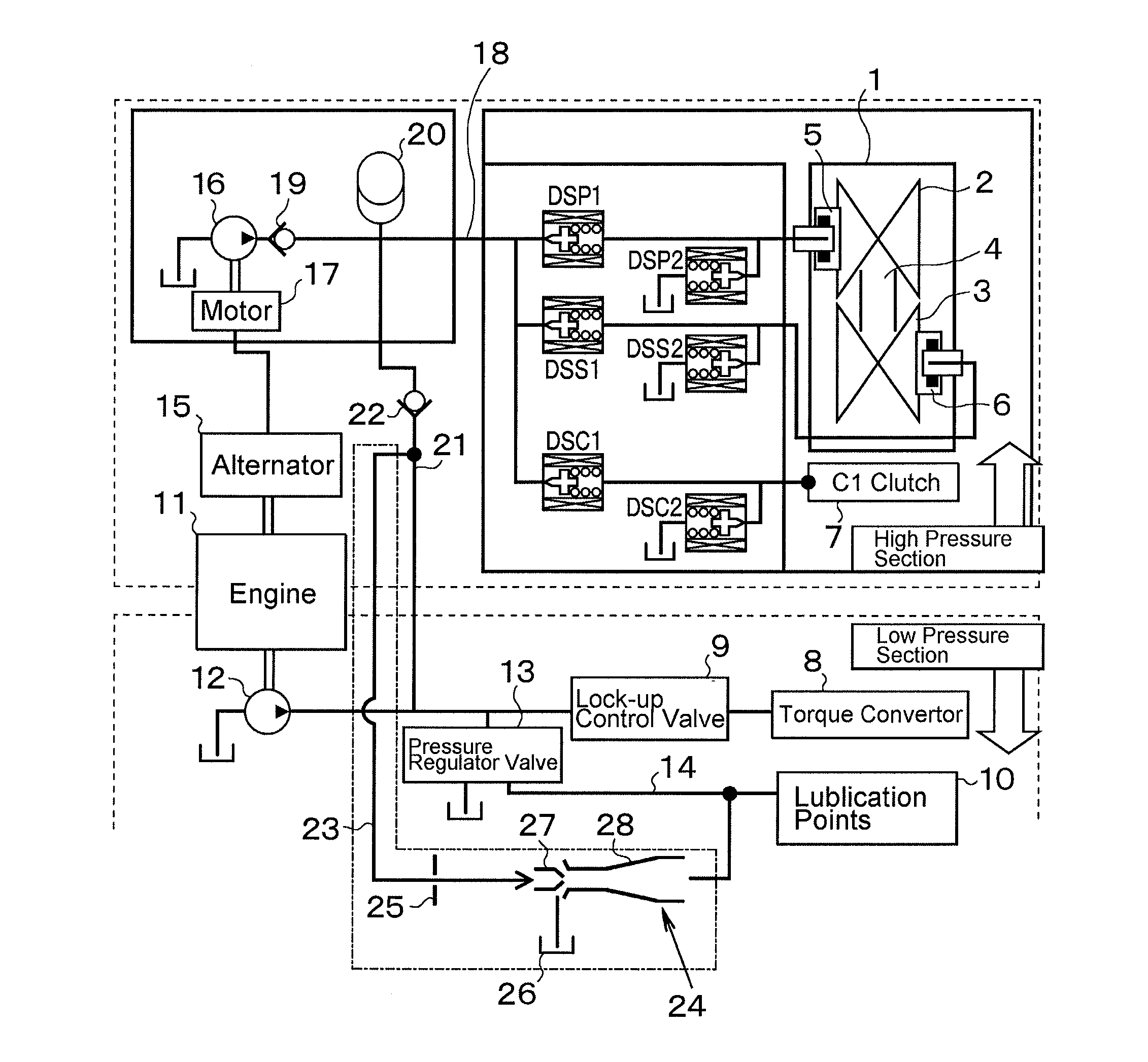
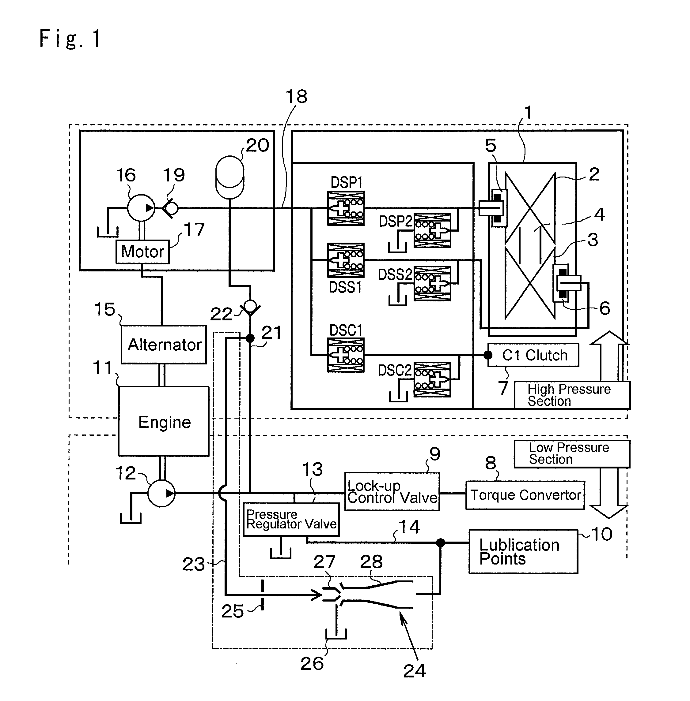
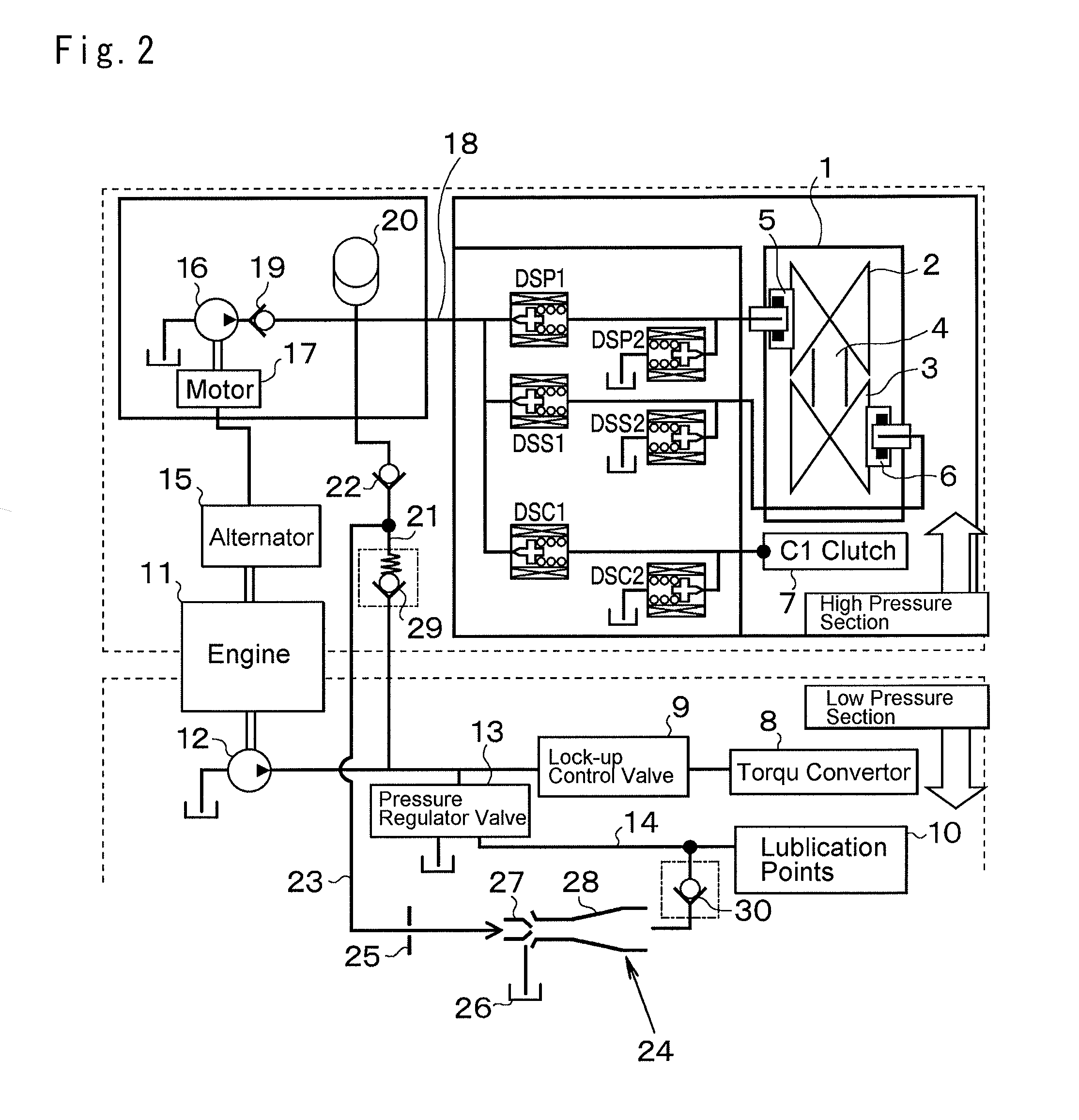
[0035]Referring now to FIG. 1, there is shown an example of applying the hydraulic control system of the invention to a continuously variable transmission used in an automobile. The continuously variable transmission 1 is a conventional belt-driven CVT comprising a drive pulley 2, a driven pulley 3 and a belt 4 mounted driveably on those pulleys 2 and 3 to transmit a torque therebetween. Each pulley 2 and 3 comprises a fixed sheave and a movable sheave being adapted for movement toward and away from the fixed sheave, and inwardly facing conical faces of the sheaves form a V-groove for holding the belt 4 therebetween. In order to move the movable sheaves axially, the pulleys 2, 3 are provided individually with hydraulic actuators 5, 6. In this preferred example, the movable sheave of the driven pulley 3 is moved axially in response to the application of pressurized hydraulic fluid to the actuator 6 thereby establishing a clamping pressure for clamping the belt 4 by the driven pulley ...


PUM


Abstract

A hydraulic control system for preventing shortage of lubricant and coolant during charging of an accumulator is disclosed. The hydraulic control system is comprised of: a hydraulic pump; an accumulator for storing fluid from the pump; and a constant delivery site which is connected to the pump in parallel with the accumulator, and which requires hydraulic fluid constantly during activation of the hydraulic pump. A pressure level of the fluid discharged from the pump is regulated to a level possible to be delivered to the accumulator, and the fluid resulting from the pressure regulation is delivered to the constant delivery site. Meanwhile, a pressure higher than that required by the constant delivery site is stored in the accumulator. The hydraulic control system is characterized by a fluid increasing means that delivers additional fluid to the constant delivery site together with the fluid resulting from said pressure regulation, when delivering the fluid discharged from the pump to the accumulator.

Description

TECHNICAL FIELD[0001]This invention relates to a hydraulic control system for delivering hydraulic fluid to various types of actuators and lubrication points, while storing hydraulic pressure in an accumulator.BACKGROUND ART[0002]Various kinds of actuating mechanisms are actuated hydraulically, and hydraulic fluid is partially used for cooling and lubrication. Usually, the hydraulic pressure is established by a hydraulic pump driven by an engine or a motor. That is, cessation of engine or motor operation will result in a loss of hydraulic pressure. In order to maintain the hydraulic pressure to continue an operation in progress in case of stopping the hydraulic pump, an accumulator is used in a conventional hydraulic system. For example, conventional hydraulic control devices are disclosed in Japanese Patent Laid-Open No. 2004-84928 and International Publication No. 2010 / 021218.[0003]The control devices disclosed in those publications are used to control a transmission. According to...

Claims


Application Information

Patent Timeline
Patent Type & Authority Applications(United States)
IPC IPC(8): F04B17/03
CPCF04B17/03F15B1/024F16H2061/0034F16H2061/0037F16H61/0031F16H61/0025
Inventor YOSHIDA, MICHIOINAGAWA, TOMOKAZU
Owner TOYOTA JIDOSHA KK
Why Eureka
Try Eureka