
Brake pressure compensation system and method thereof

a brake pressure compensation and brake pressure technology, applied in the direction of braking systems, instruments, analogue processes for specific applications, etc., can solve the problems of difficult maintenance of required negative pressure, unstable braking performance, and rapid decrease of engine negative pressure, etc., to achieve stable braking force

Inactive Publication Date: 2013-12-12
HYUNDAI MOTOR CO LTD +2
View PDF5 Cites 7 Cited by
  • Summary
  • Abstract
  • Description
  • Claims
  • Application Information

AI Technical Summary

Benefits of technology

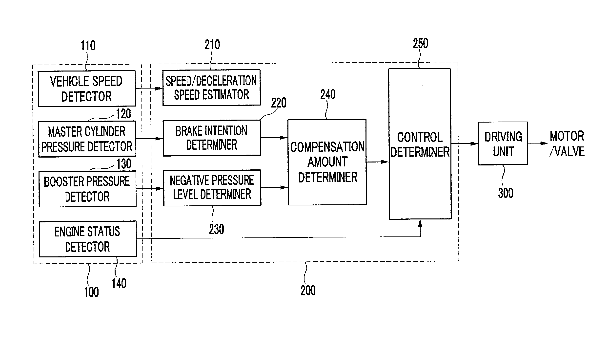
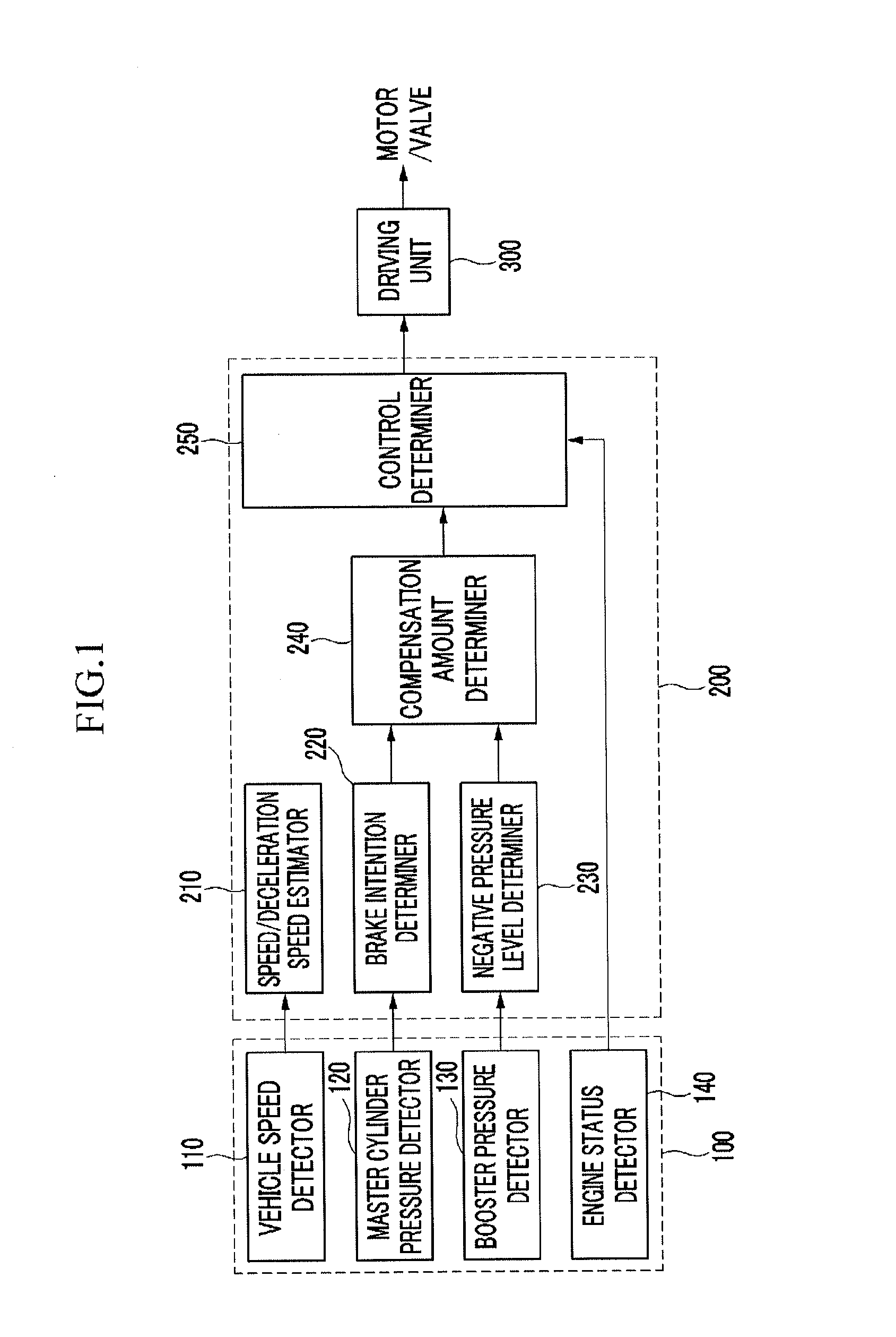
The present invention provides a hydraulic brake pressure compensation system and method that can determine the brake intention and compensate for the brake pressure by using a sensor unit that detects the pressure of the master cylinder, the vehicle speed, the booster pressure, and the engine status. The control unit analyzes the data from the sensor unit and decides the brake pressure based on the brake intention, the negative pressure of the booster, and the driving conditions. The system can provide a stable braking force and compensate for the hydraulic brake pressure in response to the brake pedal effort. The system can also include an ESC module that controls the braking force and compensates for the hydraulic brake pressure in response to the vehicle speed, the engine speed, and the driving environment. Overall, the invention provides a more efficient and effective brake pressure compensation system for vehicles.

Problems solved by technology

Therefore, as electric load is increased by using an air-conditioning system in traveling in summer, load of an alternator is increased by a charging / discharging logic and the negative pressure of the engine rapidly decreases, such that a required negative pressure is difficult to maintain and stable braking performance cannot be provided.
Since the negative pressure of an engine is influenced by the ignition timing, a method of improving the negative pressure of an engine by advancing the ignition timing has been used, but when the ignition timing is excessively advanced, many restrictions are caused, for example, in exhaust gas regulation, power performance, fuel efficiency, and NVH (Noise / Vibration / Harshness).
As another example, a method of improving the negative pressure of a booster by additionally mounting an intensifier has been used, but when it is applied to a vehicle with 1.5 L or less, excessive air passing through an IBS (Intensifier Brake System) flows into the engine and may cause malfunction of the engine.
However, as an expensive vacuum pump is added, the manufacturing cost increases and price competitiveness is deteriorated, and designing of a layout and the assembly process are complicated, such that productivity is deteriorated, and the weight increases and the load for driving the vacuum pump is allotted, such that the fuel efficiency decreases and the engine output torque reduces.
However, designing of the engine and the assembly process are complicated, such that productivity is deteriorated and the manufacturing cost is increased, which decreases price competitiveness.
Further, there is a problem in the vehicles of the related art that it is necessary to use a brake pedal sensor that detects effort of a brake pedal in order to determine On / Off of the brake pedal by a driver.

Method used


Image

  • Brake pressure compensation system and method thereof
  • Brake pressure compensation system and method thereof
  • Brake pressure compensation system and method thereof

Examples


Embodiment Construction

[0033]Reference will now be made in detail to various embodiments of the present invention(s), examples of which are illustrated in the accompanying drawings and described below. While the invention(s) will be described in conjunction with exemplary embodiments, it will be understood that the present description is not intended to limit the invention(s) to those exemplary embodiments. On the contrary, the invention(s) is / are intended to cover not only the exemplary embodiments, but also various alternatives, modifications, equivalents and other embodiments, which may be included within the spirit and scope of the invention as defined by the appended claims.

[0034]In the following detailed description, only certain exemplary embodiments of the present invention have been shown and described, simply by way of illustration.

[0035]As those skilled in the art would realize, the described embodiments may be modified in various different ways, all without departing from the spirit or scope o...


PUM


Abstract

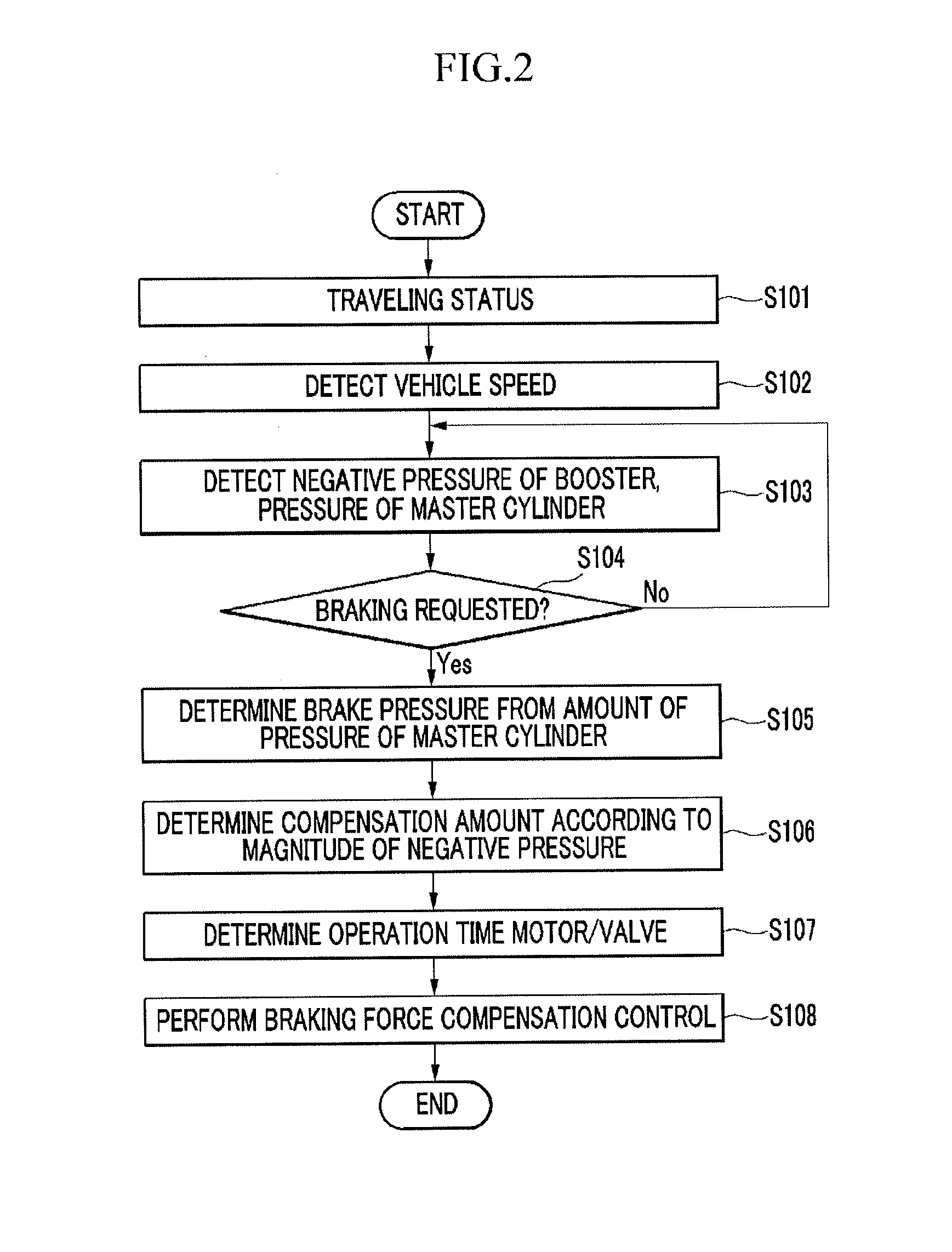
A brake pressure compensation method may include determining a vehicle speed, the magnitude of a negative pressure, and the pressure of a master cylinder, determining brake intention from a change in pressure of the master cylinder, and deciding a brake pressure from the amount of pressure of the master cylinder, determining the compensation amount of the brake pressure by applying the magnitude of a negative pressure of a booster, and performing brake control by compensating for a hydraulic brake pressure through an ESC module.

Description

CROSS-REFERENCE TO RELATED APPLICATION[0001]The present application claims priority to Korean Patent Application No. 10-2012-0062700 filed on Jun. 12, 2012, the entire contents of which is incorporated herein for all purposes by this reference.BACKGROUND OF THE INVENTION[0002]1. Field of the Invention[0003]The present invention relates to a hydraulic brake pressure compensation system. More particularly, the present invention relates to a hydraulic brake pressure compensation system that determines braking intention and brake pressure and allows providing stable braking force by compensating for hydraulic brake pressure with an ECU module, without a brake pedal effort sensor, and a method thereof.[0004]2. Description of Related Art[0005]Vehicles are equipped with a brake system that decelerates or stops the vehicles, if necessary, when the vehicles travel.[0006]The brake system generates a braking force by converting the kinetic energy of a vehicle into heat energy, using friction f...

Claims


Application Information

Patent Timeline
Patent Type & Authority Applications(United States)
IPC IPC(8): B60T8/44
CPCB60T8/442B60T8/441F16D65/14B60T13/66
Inventor KIM, TAEG JORYU, SEONG-YON
Owner HYUNDAI MOTOR CO LTD
Learn More