
Modular Structure, Modular Panel To Make Said Modular Structure And Corresponding Method To Make Said Modular Structure

a technology of modular structure and modular panel, which is applied in the direction of solar heat collectors with working fluids, photovoltaics, solar heat collectors for particular environments, etc., can solve the problems of large bulk of additional structures, high complexity of making roofs, and negative effects on the time and cost of production of roofs, so as to facilitate assembly, dismantling and maintenance of roofs. , the effect of simplifying the configuration

Inactive Publication Date: 2013-12-19
MAS
View PDF55 Cites 35 Cited by
  • Summary
  • Abstract
  • Description
  • Claims
  • Application Information

AI Technical Summary

Benefits of technology

The present invention provides modular panels for roofs and walls that can incorporate alternative and / or renewable energy sources, while also being self-supporting and cost-effective. The design simplifies assembly, dismantling, and maintenance operations, reducing the need for additional support elements. The panels can also optimize the installation and maintenance of electric, fluidic, and other equipment, reducing time and costs. The connection plate ensures optimal self-supporting characteristics on the structure, facilitating assembly, dismantling, and maintenance operations. The abutment surface strengthens the clamping of adjacent panels, even if the structure is altered in size. Overall, the invention provides a simplified and cost-effective solution for creating stable and space-efficient roof and wall structures.

Problems solved by technology

This has a negative affect on both the times and costs of production of the roofs, which are high, as well as on the complexity of making the roof itself.
One disadvantage consists in the great bulk of the additional structures, which entails a certain complexity and difficulty in integrating them with the part of the roof which is already there.
Another disadvantage is the lack of connection elements between the covering elements of the roof and / or the use of materials with little capacity of absorbing elastic energy, with consequent poor anti-seismic characteristics, which may have to be to improved with additional strategies which are equally burdensome in terms of time and cost.
However, one disadvantage of the known modular panel consists in the complexity of the presence of two shells to be coupled in the single panel and in the connection system between a plurality of the same panels to form a roof There is also complexity in the disposition of the fluidic and electric connections relating to one or more panels.
This disadvantage causes difficulties in the assembly method of the panels to make the roof.

Method used


Image

  • Modular Structure, Modular Panel To Make Said Modular Structure And Corresponding Method To Make Said Modular Structure
  • Modular Structure, Modular Panel To Make Said Modular Structure And Corresponding Method To Make Said Modular Structure
  • Modular Structure, Modular Panel To Make Said Modular Structure And Corresponding Method To Make Said Modular Structure

Examples


Embodiment Construction

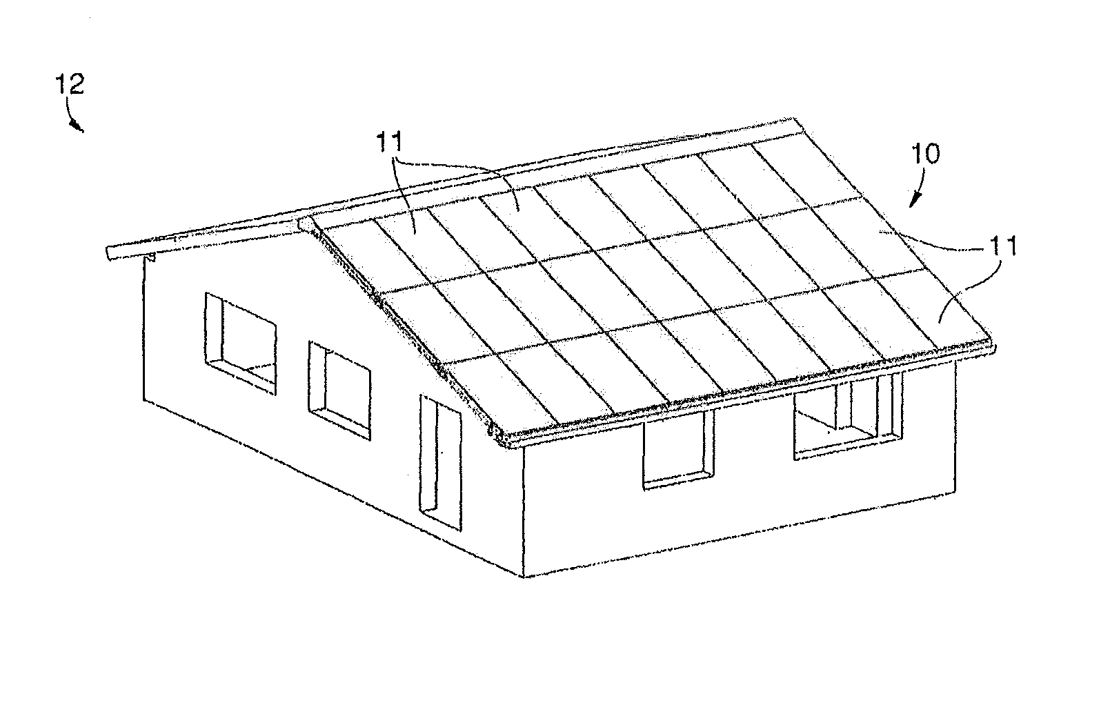
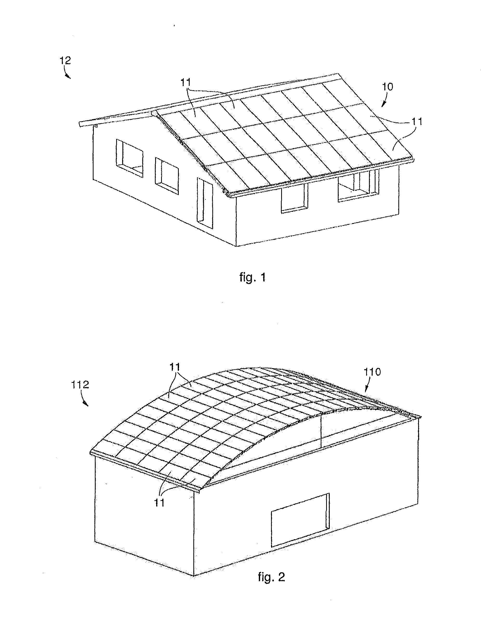
[0064]With reference to FIG. 1, a sloping roof 10 is shown, according to the present invention, of a building 12 which in this case can be a house or a small construction of the industrial type.

[0065]The roof 10 comprises a plurality of modular panels 11, in this case the same as each other and disposed adjacent, to form a self-supporting, sloping structure.

[0066]As well as roofs for houses and small constructions, which are typically sloping, the modular panels 11 can be used to make the roof of bigger buildings 112, where often a self-supporting vaulted roof 110 is used, as shown in FIG. 2.

[0067]Both the roofs 10 and 110 comprise modular panels 11 of a rectangular shape which are all the same, but this does not exclude the possibility that they may be made in another geometric shape.

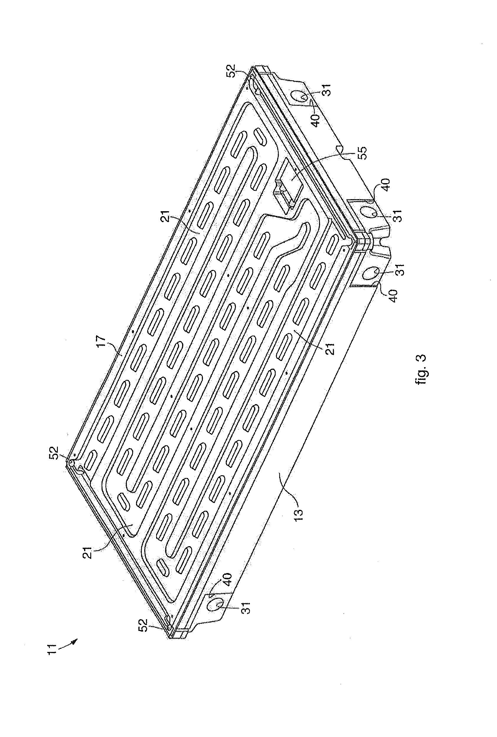
[0068]In this case, each modular panel 11 comprises an external shell 13 and a filling element 14 (FIGS. 3 and 4), both made of a moldable plastic material, such as for example a polymer material or si...


PUM


Abstract

Structure, such as a roof or a wall, comprising a plurality of modular panels (11). Each modular panel (11) has a shell (13) and a filling element (14) coupled with each other and defining at least a compartment (24, 25) for the disposition of a heat-carrying fluid and / or of fluidic and electric connection cables. Connection means are provided between one modular panel (11) and one or more adjacent modular panels (11).

Description

CROSS-REFERENCE TO RELATED APPLICATIONS[0001]This application claims the benefit under 35 U.S.C. §119(e) of U.S. Provisional Patent Application No. 61 / 660,069, filed Jun. 15, 2012, the entire disclosure of which is incorporated herein by reference.BACKGROUND OF THE INVENTION[0002]1. Field of the Invention[0003]The present invention concerns a structure, such as for example a roof or a wall of a building, of the modular type and consisting of a plurality of panels, functionally and mechanically connected with each other.[0004]The invention also concerns the panel used to make the structure, and to the corresponding method to make the structure.[0005]In particular, the present invention can be applied in the building sector when it is intended to make a closed environment or room, acoustically and / or thermally insulated, possibly having anti-seismic characteristics, and / or inside which significant consumption of electric and / or heat energy is expected, and it is desired to partly use ...

Claims


Application Information

Patent Timeline
IPC IPC(8): E04C2/52H01L31/042
CPCE04C2/521H01L31/042H02S40/44H02S30/10H02S20/23Y02B10/20Y02E10/60Y02E10/44Y02B10/70Y02E10/47F24S60/30F24S80/30F24S20/67F24S25/13F24S10/502F24S80/457F24S25/67Y02E10/50Y02B10/10
Inventor DAMO, MARIO
Owner MAS
Learn More