Rubber composition for tire valve and tire valve

Inactive Publication Date: 2013-12-19
THE GATES CORP
View PDF14 Cites 8 Cited by
  • Summary
  • Abstract
  • Description
  • Claims
  • Application Information

AI Technical Summary

Benefits of technology

[0007]The present invention is directed to systems and methods which provide snap-in tire valves with improved high speed

Problems solved by technology

The added mass of the sensor results in much higher demands placed on the rubber sealing member of the valve.
Thus, applications of TPMS can experience accelerations of up to 1400 Gs and operating temperatures of up to 100

Method used


Image

  • Rubber composition for tire valve and tire valve
  • Rubber composition for tire valve and tire valve

Examples


Example

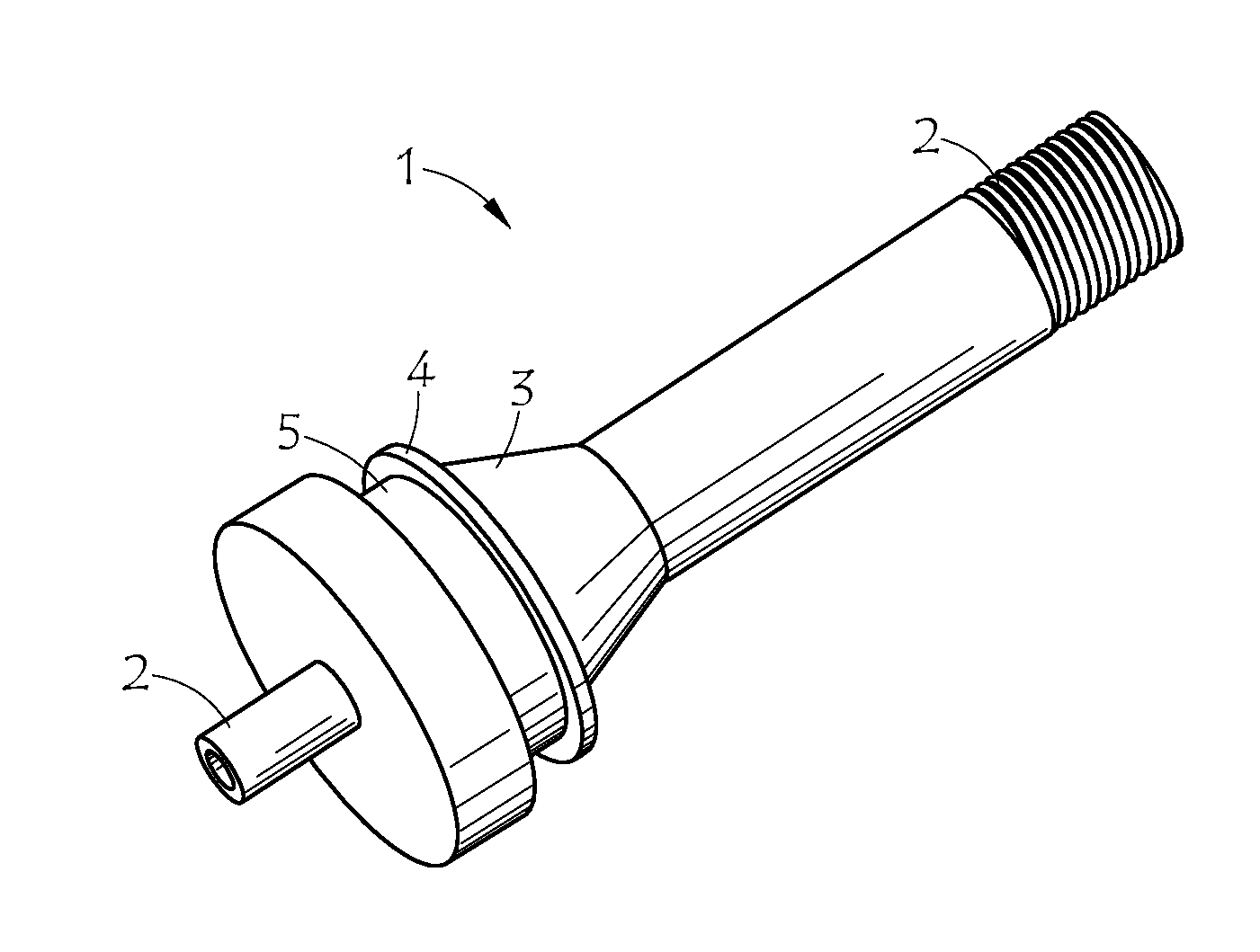
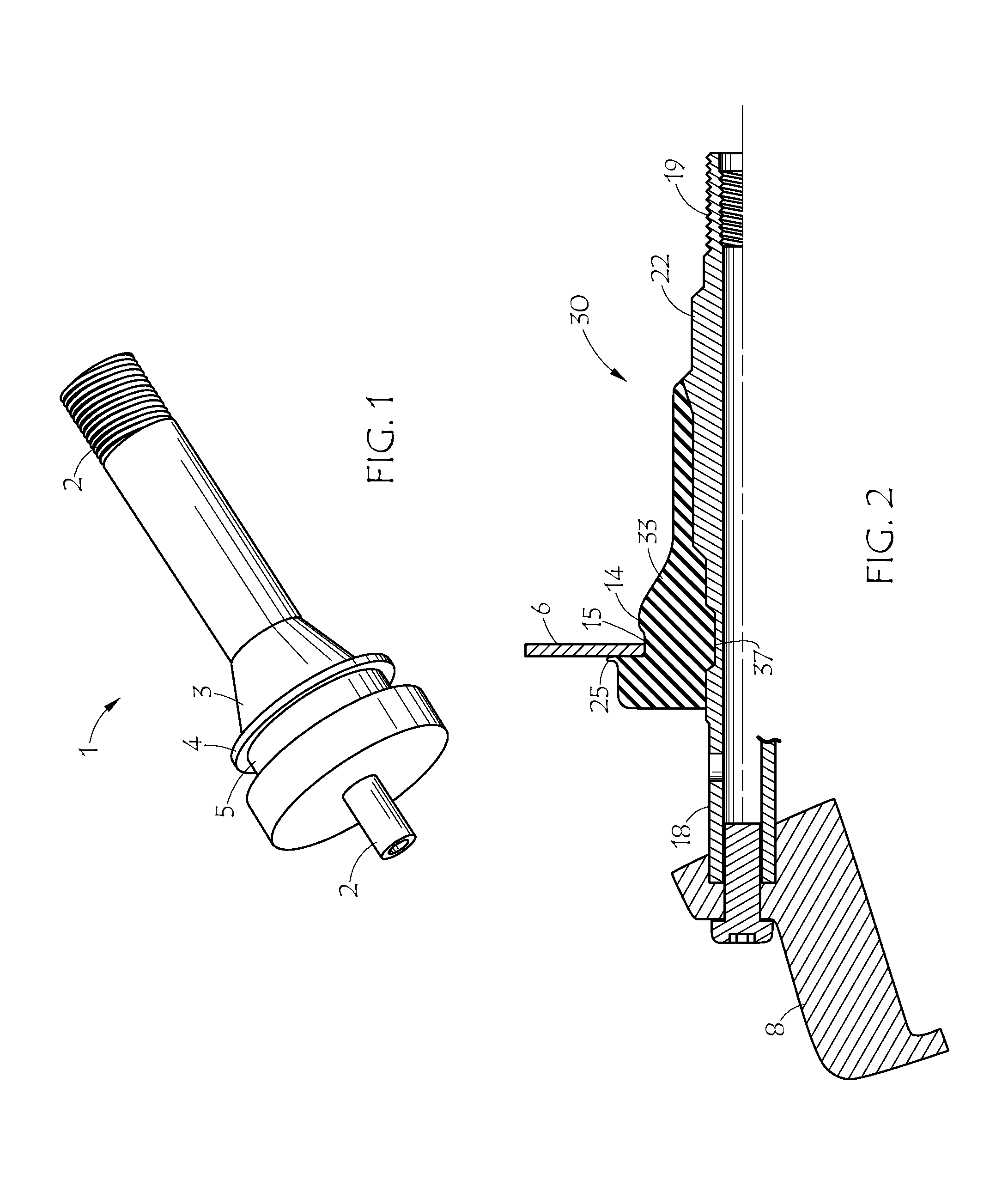
[0022]FIG. 1 shows an embodiment of a snap-in tire valve. Tire valve 1 includes brass valve body 2 arranged along the axis thereof and resilient member 3 over-molded around the outside surface of the brass valve body. The resilient member is shaped so that it can be inserted into a valve opening or hole in a wheel rim (not shown). Rib 4 is larger than the valve hole diameter, so that the rib must deflect as the tire valve is pulled though the hole. Groove 5 has an outside diameter somewhat bigger than the hole so that when the edge of the hole snaps into the groove, the resilient member residing between the edge of the hole and the brass valve body, i.e., the resilient member in the vicinity of the groove, remains in compression to effect an air-tight seal between the valve body and the wheel rim. In other words, groove 5 provides the sealing surface of the tire valve. The resilient member conventionally consisted of a conventional sulfur-cured, rubber composition. According to the ...


PUM

PropertyMeasurementUnit
Fractionaaaaaaaaaa
Fractionaaaaaaaaaa
Fractionaaaaaaaaaa

Abstract

A tire valve for snap-in mounting in a valve hole in a wheel rim, having a resilient member surrounding and bonded to at least a portion of the valve body, wherein the resilient member is a vulcanized rubber composition comprising ethylene alpha-olefin elastomer, carbon black, high-density inert filler, and an efficient vulcanization cure system.

Description

BACKGROUND OF THE INVENTION[0001]1. Field of the Invention[0002]This invention relates generally to a tire valve, more particularly to a rubber composition for a snap-in tire valve, and specifically to a snap-in tire valve with an EV-cured, EPDM, rubber composition.[0003]2. Description of the Prior Art[0004]Tire valves of the snap-in type are known. A shaped resilient rubber sealing member is commonly over-molded around a brass valve body. The seal shape generally includes a circumferential ridge or rib that must be compressed or otherwise deformed to let the seal snap into the valve hole in the wheel rim and a groove that retains the valve in the valve hole. The resilient seal then supports the valve body and seals the hole. The support and sealing functions are expected to last the life of the tire. U.S. Pat. Nos. 3,287,485 and 3,670,688 disclose examples of valves of rubber and brass that snap into a wheel rim. The '485 patent discloses a styrene-butadiene rubber (SBR) formulatio...

Claims


Application Information

Patent Timeline
IPC IPC(8): B60C29/02B29C70/68
CPCB29C70/72B60C1/00B60C29/005B60C29/02
Inventor BURLETT, DONALD JAMES
Owner THE GATES CORP
Why Eureka
Try Eureka