Multipair differential signal transmission cable

a signal transmission cable and differential technology, applied in the direction of coaxial cables/analogue cables, cables with twisted pairs/quads, cables, etc., can solve the problem of signal quality degradation

Active Publication Date: 2013-12-19
HITACHI METALS LTD
View PDF19 Cites 22 Cited by
  • Summary
  • Abstract
  • Description
  • Claims
  • Application Information

AI Technical Summary

Benefits of technology

[0032]According to one embodiment of the invention, a multipair differential signal transmission cable is constructed such that the overlapping portion is arranged so as not to face the adjacent differential signal transmission cable. The differential signal transmission cables are twisted such that the overlapping portion preferably faces the outside of the multipair differe

Problems solved by technology

The multipair differential signal transmission cable disclosed in JP-A-2004-08718

Method used


Image

  • Multipair differential signal transmission cable
  • Multipair differential signal transmission cable
  • Multipair differential signal transmission cable

Examples


first embodiment

of the Invention

[0041]Structure of Multipair Differential Signal Transmission

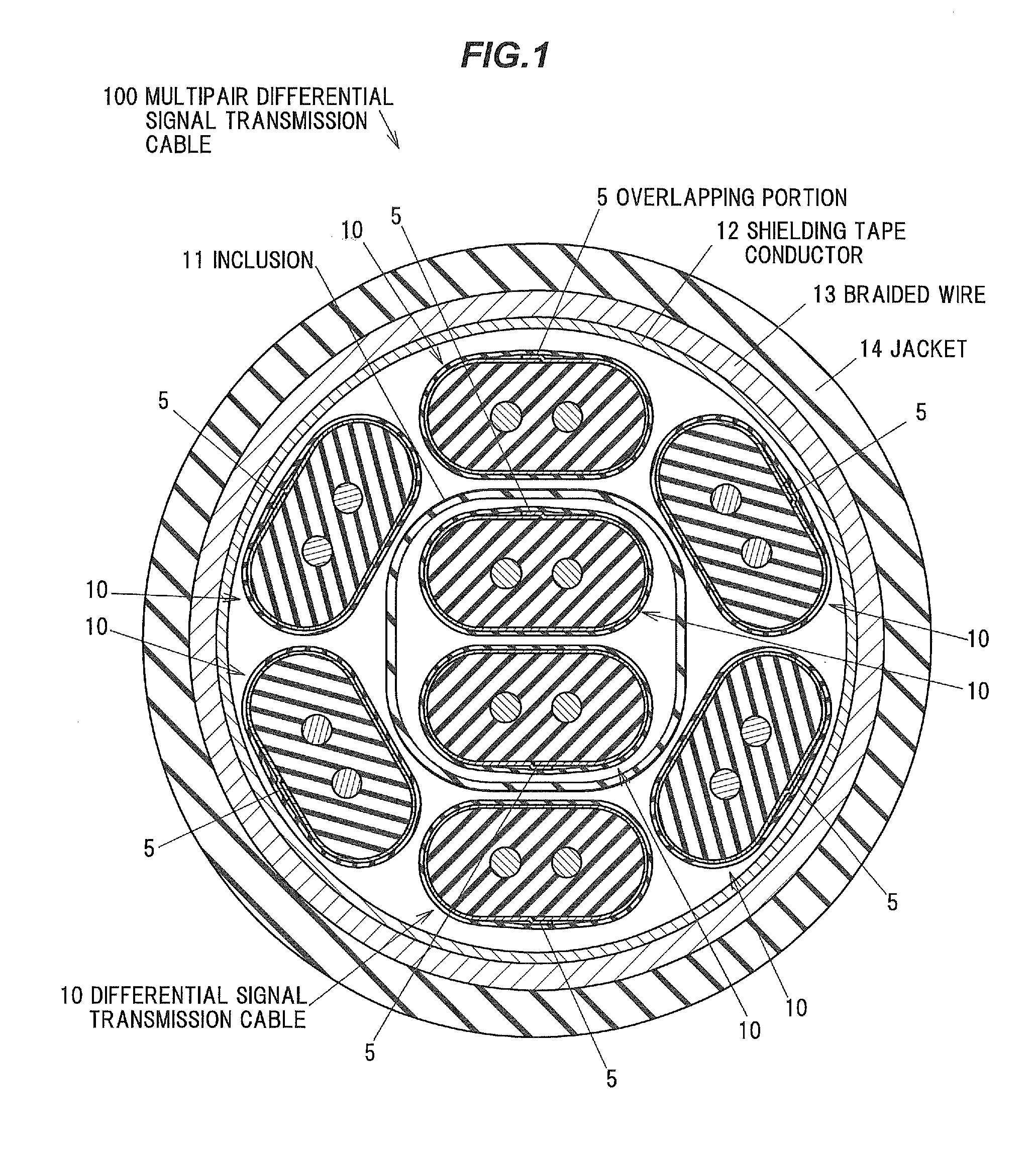
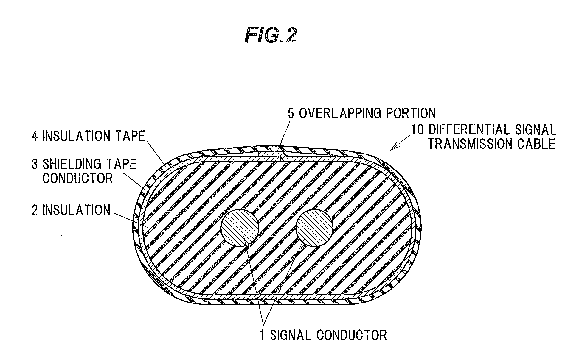
[0042]FIG. 1 is a cross sectional view showing a cross-section structure of a multipair differential signal transmission cable in a first embodiment of the invention and FIG. 2 is a cross sectional view showing a cross-section structure of a differential signal transmission cable used for the multipair differential signal transmission cable in the first embodiment of the invention.

[0043]A multipair differential signal transmission cable 100 in the first embodiment is formed by bundling and twisting plural differential signal transmission cables 10 each composed of two signal conductors 1 as a differential pair, an insulation 2 covering therearound and a shielding tape conductor 3 provided on a periphery of the insulation 2. The shielding tape conductor 3 is longitudinally lapped (also referred to as cigarette roll) so as to have an overlapping portion 5 which extends in a cable longitudinal direction. The m...

second embodiment

of the Invention

[0060]Structure of Multipair Differential Signal Transmission

[0061]FIG. 4 is a cross sectional view showing a cross-section structure of a multipair differential signal transmission cable in a second embodiment of the invention.

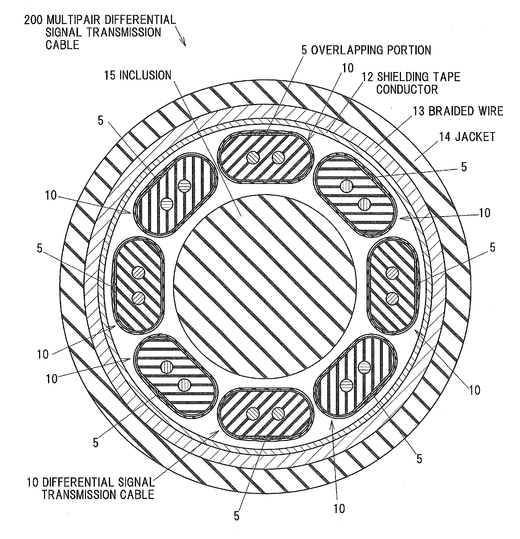
[0062]In a multipair differential signal transmission cable 200 in the second embodiment, an inclusion 15 is arranged in the middle of the multipair differential signal transmission cable 200 as viewed in a cross section and eight differential signal transmission cables 10 are arranged around the inclusion 15 at substantially equal intervals.

[0063]The remaining configuration is the same as the first embodiment and the explanation thereof will be omitted.

[0064]Effects of the Second Embodiment of the Invention

[0065]The second embodiment achieves the same effects as the first embodiment except a disadvantage in that a cable is thicker than that of the first embodiment.

example

[0066]By using the following method, it was confirmed that leakage of electromagnetic energy from a surface having the overlapping portion 5 of the shielding tape conductor 3 is larger than that from an opposite surface.

[0067]FIG. 5 is a schematic view showing an evaluation system of magnetic near-field strength in the differential signal transmission cable.

[0068]In a measuring system which is calibrated so that end portions of cables 22 connected to a network analyzer 21 are on a calibration surface 30, a signal in mixed-mode (a signal propagation mode defined by a differential mode and a common mode) is input, through a cable termination tool 25, to the differential signal transmission cable 10 as an object to be measured. At this time, in order to reduce unwanted reflected signals generated on an open end side of the differential signal transmission cable 10 as an object to be measured, anti-reflective treatment is performed on a far end side of the differential signal transmissi...


PUM


Abstract

A multipair differential signal transmission cable includes a plurality of differential signal transmission cables being bundled and each including two signal conductors as a differential pair covered with an insulation and a first shielding tape conductor provided therearound. The first shielding tape conductor is longitudinally lapped so as to have an overlapping portion in a cable longitudinal direction. The plurality of differential signal transmission cables include at least one or more pairs of two adjacent differential signal transmission cables. The two adjacent differential signal transmission cables are arranged such that the overlapping portion of one of the two adjacent differential signal transmission cables does not face the other of the two adjacent differential signal transmission cables.

Description

[0001]The present application is based on Japanese patent application No. 2012-138037 filed on Jun. 19, 2012, the entire contents of which are incorporated herein by reference.BACKGROUND OF THE INVENTION[0002]1. Field of the Invention[0003]The invention relates to a multipair differential signal transmission cable.[0004]2. Description of the Related Art[0005]A multipair differential signal transmission cable is known that is formed by bundling plural differential signal transmission cables (see, e.g., JP-A-2004-087189).[0006]JP-A-2004-087189 (FIGS. 2 and 6) discloses an assembled transmission cable (a multipair differential signal transmission cable) formed by assembling plural transmission cables (differential signal transmission cables) each having a signal line pair as a pair of insulated wires each composed of a signal line covered with an insulation layer, a drain wire, a shield material covering the pair of signal lines as well as the drain wire and a cushioning material cover...

Claims


Application Information

Patent Timeline
IPC IPC(8): H01B11/08
CPCH01B11/085H01B11/1826H01B11/20
Inventor NONEN, HIDEKISUGIYAMA, TAKAHIRO
Owner HITACHI METALS LTD
Why Eureka
Try Eureka