Wind turbine blade tubular spar fabricating method

Inactive Publication Date: 2013-12-19
WINDFIN
View PDF9 Cites 10 Cited by
  • Summary
  • Abstract
  • Description
  • Claims
  • Application Information

AI Technical Summary

Benefits of technology

[0010]It is one advantage of the present disclosure to provide a wind turbine blade tubular spar fabricating method configured to eliminate certain of the drawbacks of certain of the known art.
[0011]Another advantage of the present disclosure is to provi

Problems solved by technology

This solution has the drawback of producing webs with a break along the centreline, and of not allowing use, a

Method used


Image

  • Wind turbine blade tubular spar fabricating method
  • Wind turbine blade tubular spar fabricating method
  • Wind turbine blade tubular spar fabricating method

Examples


Embodiment Construction

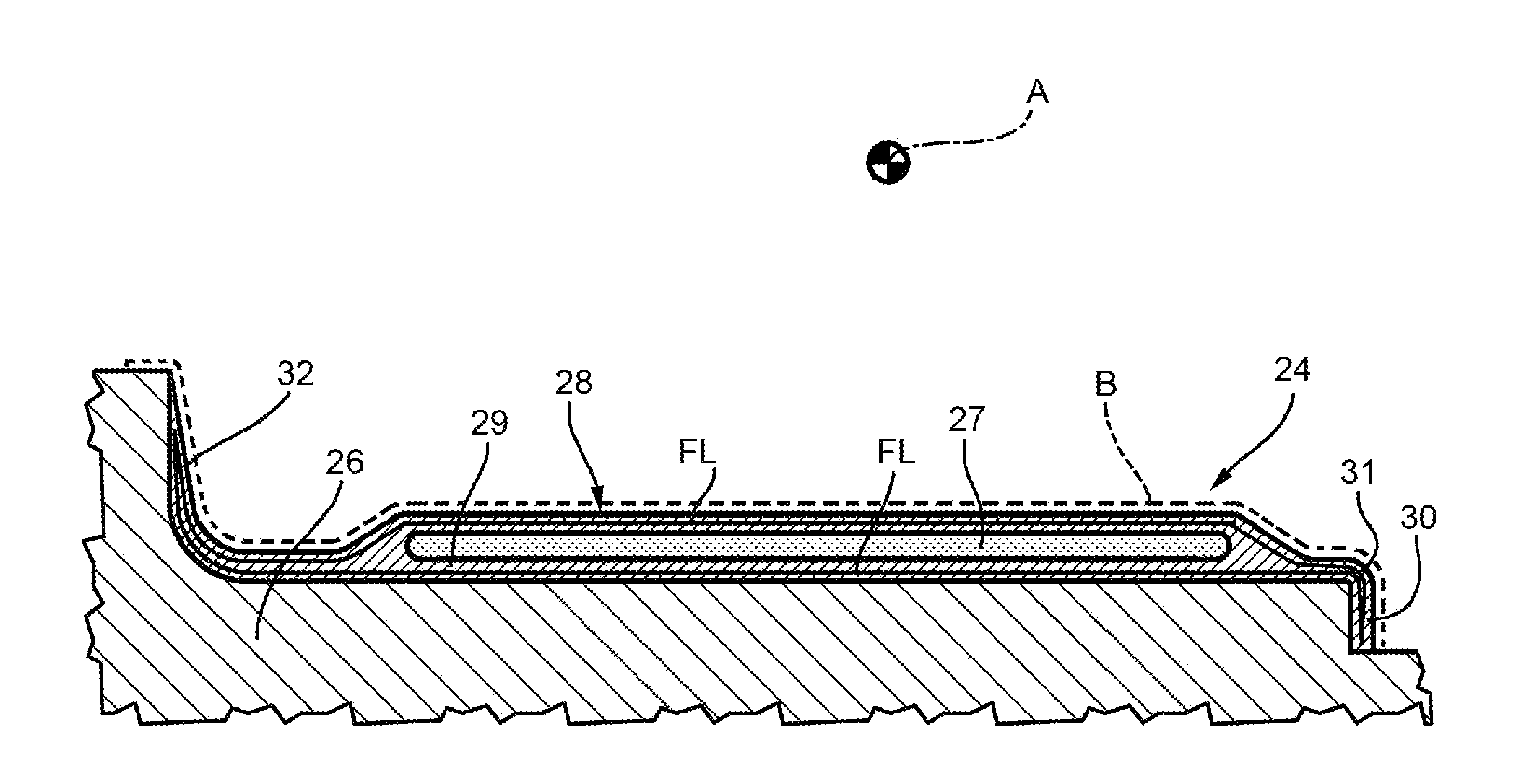
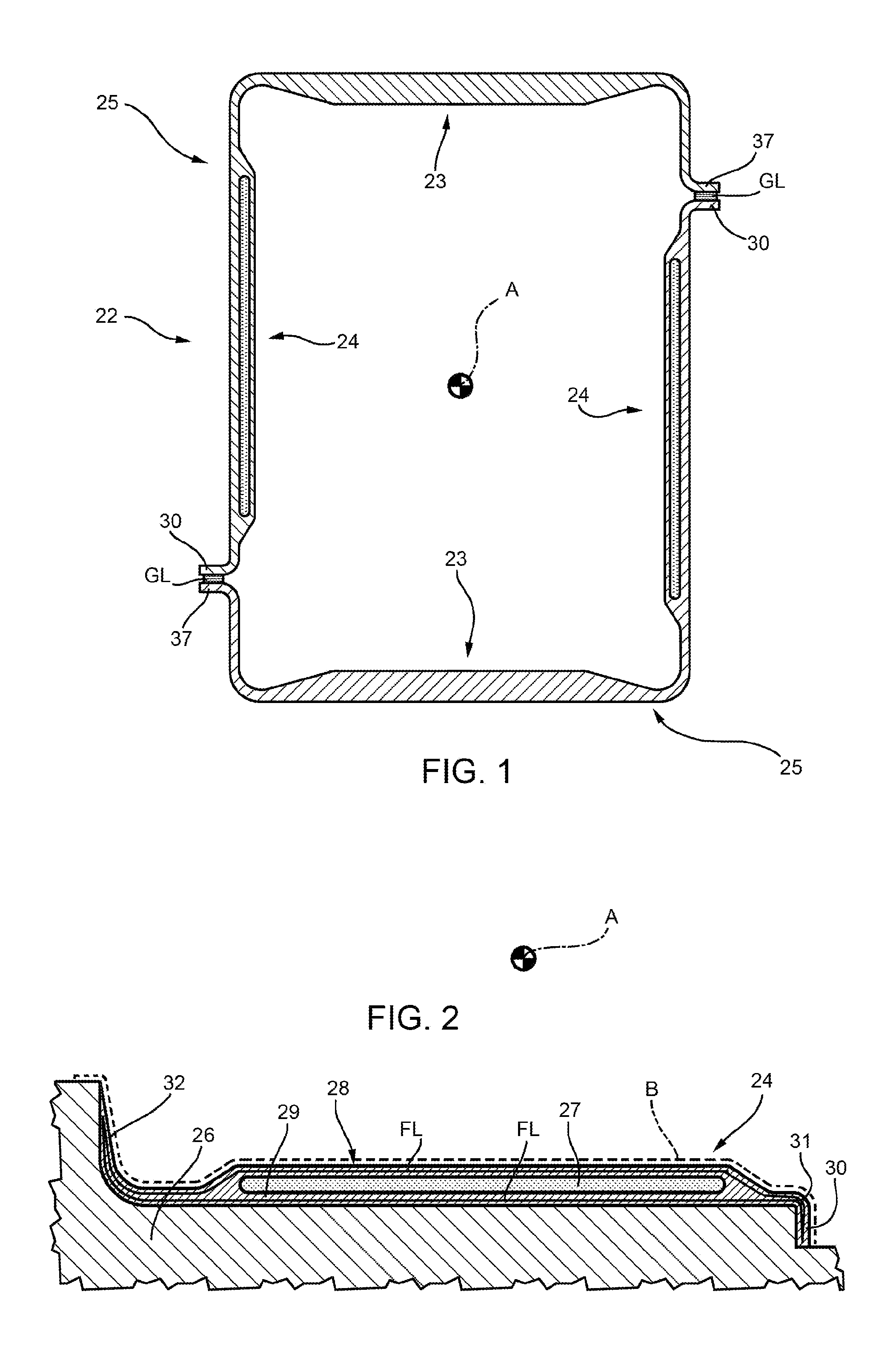
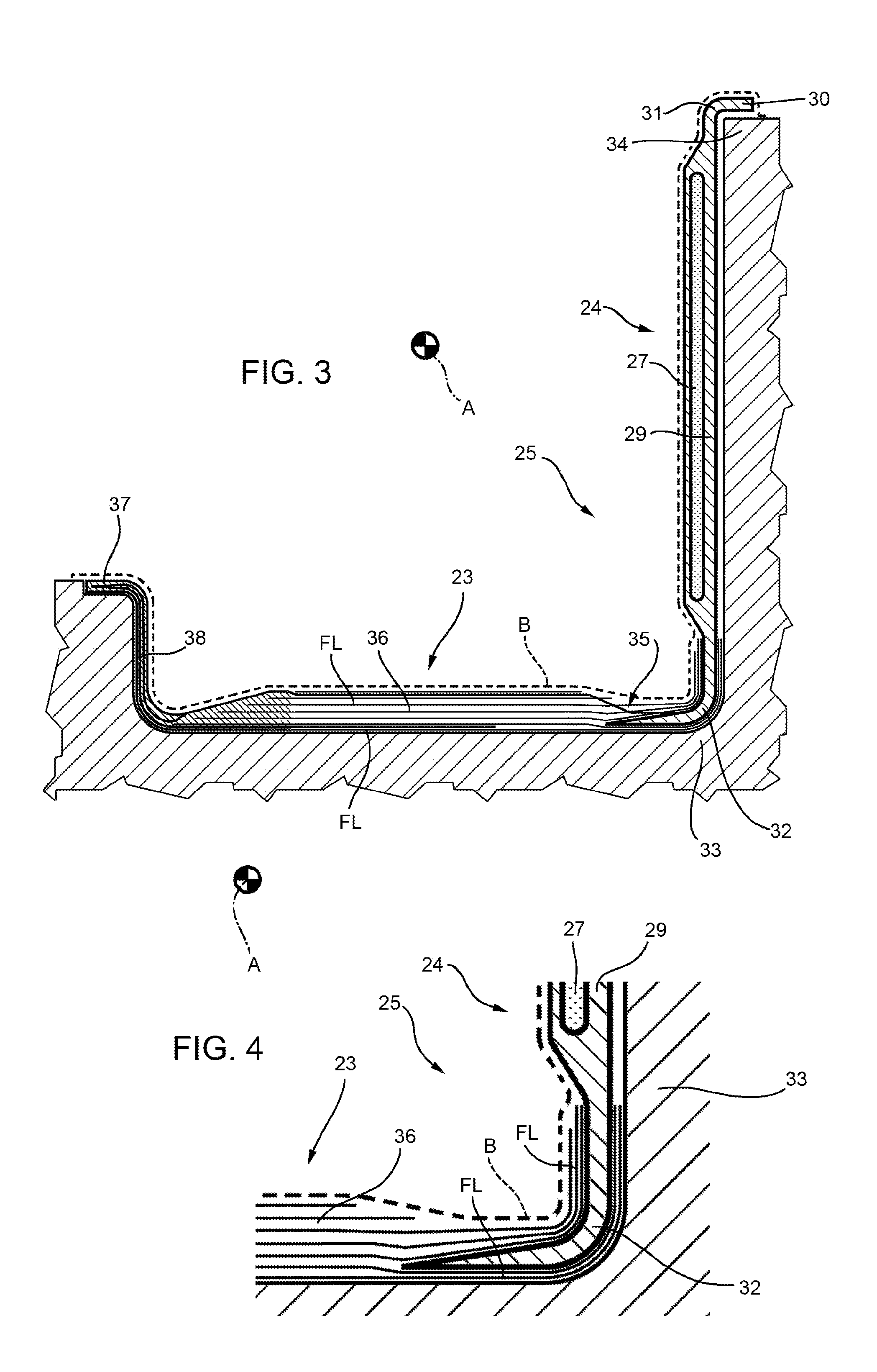
[0044]Referring now to the example embodiments of the present disclosure illustrated in FIGS. 1 to 12, number 22 in FIG. 1 indicates as a whole a tubular spar configured to support a hollow blade (not shown) of a wind turbine (not shown). In the example shown, tubular spar 22 extends along an axis A, and comprises two opposite caps 23 configured to withstand bending stress, and two opposite webs 24 configured to withstand shear stress. Caps 23 and webs 24 are made of polymer material reinforced with carbon or glass or other suitable fibers, which are normally preassembled in layers with a designated or given orientation. The number or quantity of fiber layers and orientation of the fibers depend on the application, and on the type and degree of stress to which caps 23 and webs 24 are subjected in use. Each cap 23 is joined to a respective web 24 to form an L-shaped structure 25, which is, connected to another L-shaped structure 25 by layers of glue GL to form tubular spar 22.

[0045]T...


PUM

PropertyMeasurementUnit
Angleaaaaaaaaaa
Moldableaaaaaaaaaa

Abstract

A method of fabricating a wind turbine blade tubular spar, wherein the tubular spar extends along a designated axis, is made of reinforced polymer material having fibers arranged in at least two directions, and a polymer matrix incorporating the fibers, and has two caps and two webs; the method including the steps of: molding and cross-linking at least part of a cap or web in composite material; molding and cross-linking an L-shaped structure, which has two opposite parallel flanges, and at least partly incorporates the previously molded, cross-linked cap or web of composite material; repeating the above steps to mold and cross-link a further L-shaped structure; and joining the two cross-linked, L-shaped structures, with the flanges positioned facing in pairs.

Description

PRIORITY CLAIM[0001]This application is a national stage application of PCT / IB2011 / 054314, filed on Sep. 30, 2011, which claims the benefit of and priority to Italian Patent Application No. MI2010A 001796, filed on Sep. 30, 2010, the entire contents of which are each incorporated by reference herein.BACKGROUND[0002]Certain known wind turbine blades comprise a root connecting the blade to the hub; a supporting frame connected to the root; and a shell defining the blade section and fitted to the frame.[0003]Wind turbine blades can span considerable lengths, and are subjected to severe stress by the wind, which is transmitted from the shell to the frame, and which the frame is specially designed to withstand.[0004]As shown in U.S. Published Patent Application No. 2009 / 0136355 A1 and U.S. Published Patent Application No. 2010 / 0068065 A1, the supporting frame substantially comprises a tubular, substantially rectangular-section spar comprising two opposite parallel caps connected to the s...

Claims


Application Information

Patent Timeline
IPC IPC(8): B29D99/00
CPCB29D99/0025B29C70/443B29L2031/085F03D1/0675F05B2280/6003Y02E10/72Y02P70/50
Inventor CASAZZA, MATTEOVERDESCA, MATTEOSABBADIN, AMEDEOBABY, PHILIP
Owner WINDFIN
Why Eureka
Try Eureka