
Multiple viewpoint image display device

a multi-viewpoint, image display technology, applied in the direction of color television details, instruments, electrical appliances, etc., can solve the problems of inability to use such technology, greatly reduced horizontal resolution, and inconvenient viewing for viewers, so as to prevent the deterioration of picture quality

Inactive Publication Date: 2013-12-19
SAMSUNG ELECTRONICS CO LTD
View PDF11 Cites 30 Cited by
  • Summary
  • Abstract
  • Description
  • Claims
  • Application Information

AI Technical Summary

Benefits of technology

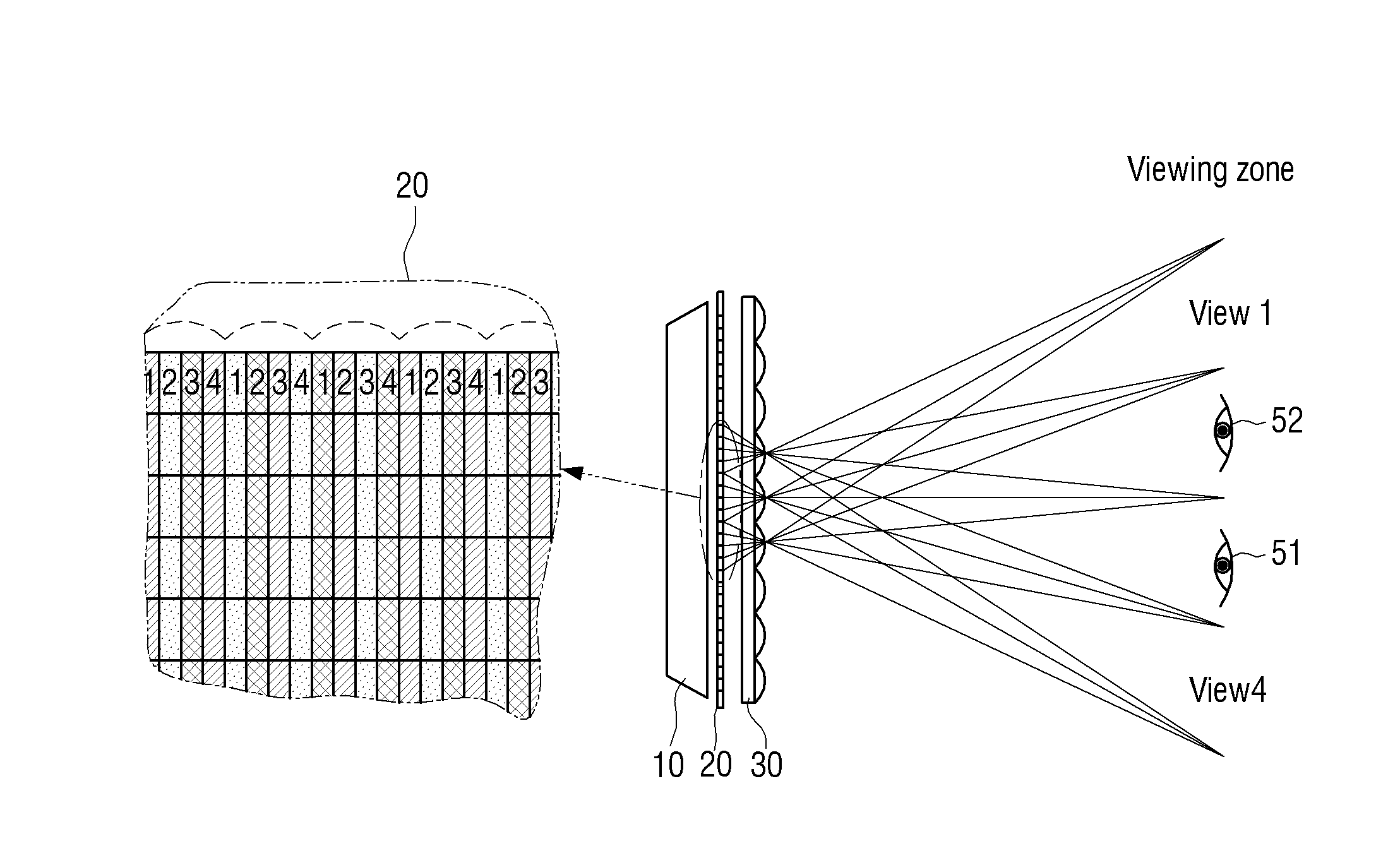
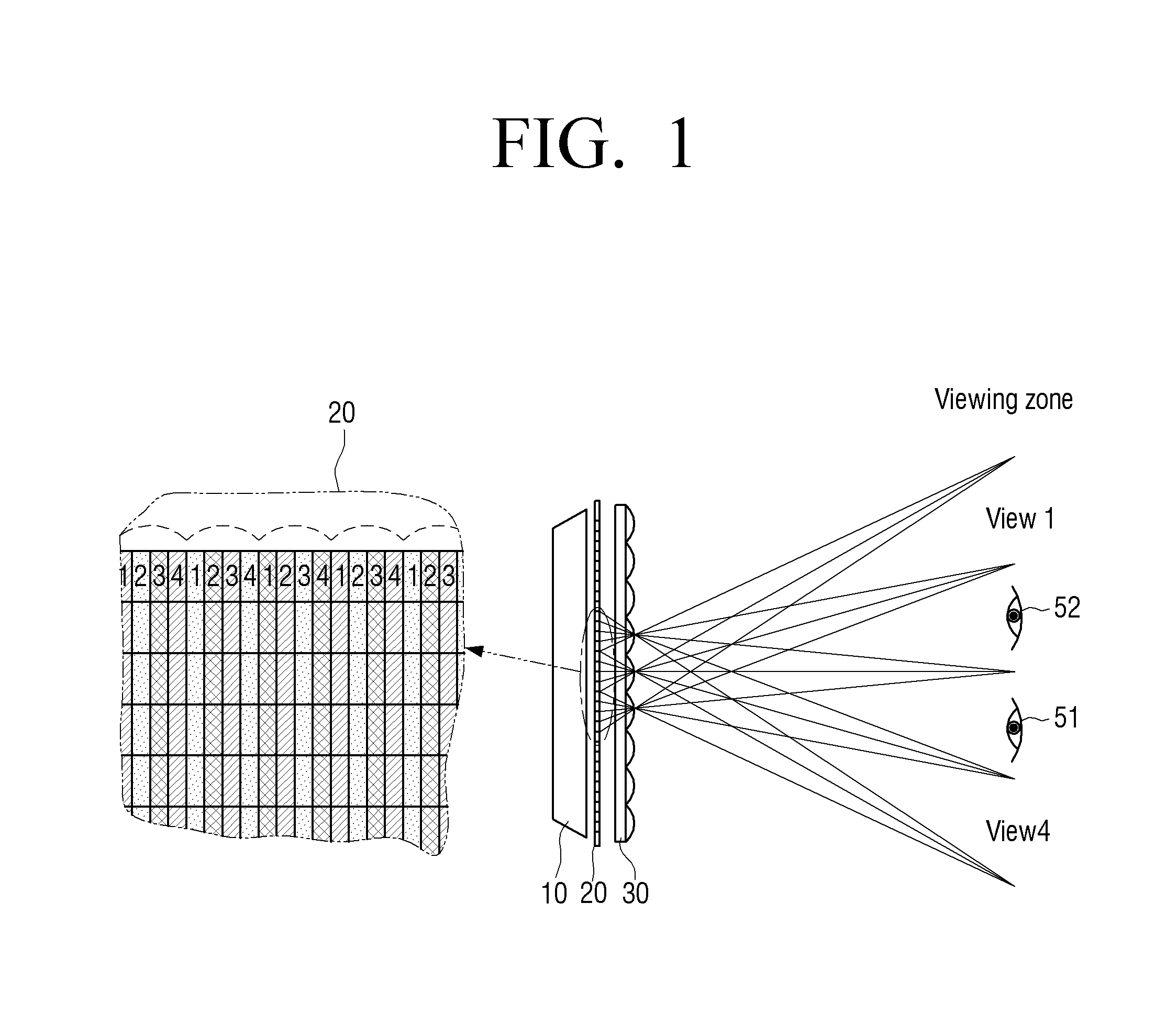
The invention provides a multi-viewpoint image display device that can effectively disperse a loss of resolution between the vertical and horizontal resolutions. The device includes an image panel, a mask portion, and a parallax portion. The mask portion masks a portion of each pixel, and the parallax portion generates a plurality of viewpoint images directed toward different viewpoints. The resolution of each viewpoint image is reduced in both a column direction and a row direction as compared to the generated image. The invention effectively disperses the loss of resolution in both the vertical and horizontal directions, preventing deterioration of picture quality.

Problems solved by technology

The glasses type system can provide a satisfactory 3D effect, but wearing glasses may cause inconvenience to a viewer.
However, in the 3D display device in the related art, since a plurality of images are separated by vertical columns to be displayed, the vertical resolution is maintained, but the horizontal resolution is greatly reduced.
However, this technology has the problem that a Liquid Crystal Display (LCD) panel in the related art having a general pixel arrangement is unable to be used for such technology.
According to this method, however, due to the difference in arrangement between the pixel columns and the lenticular lens, light emitted from other pixels overlap each other, and crosstalk occurs between the images.
Accordingly, if the crosstalk is increased, the picture quality is deteriorated.
According to the related art as described above, it is unable to effectively solve the above-described problem of the deterioration of the horizontal resolution.

Method used


Image

  • Multiple viewpoint image display device
  • Multiple viewpoint image display device
  • Multiple viewpoint image display device

Examples


Embodiment Construction

[0054]Hereinafter, exemplary embodiments will be described in more detail with reference to the accompanying drawings, in which like reference numerals correspond to like elements throughout.

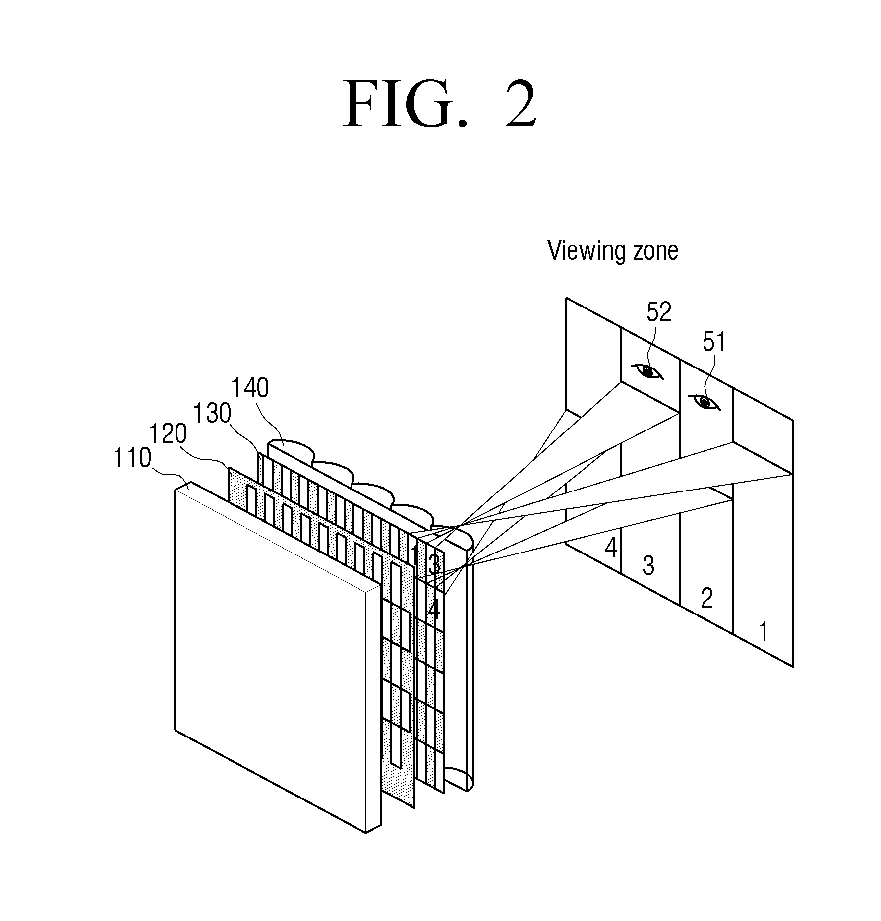
[0055]FIG. 2 is a view illustrating a configuration of a multi-viewpoint image display device according to an exemplary embodiment. The multi-viewpoint image display device of FIG. 2 is a device that performs a stereoscopic display in a non-glasses method. The multi-viewpoint image display device of FIG. 2 may be implemented by various types of display devices, such as TVs, monitors, mobile phones, PDAs, set-top PCs, tablet PCs, digital photo frames, and kiosks

[0056]Referring to FIG. 2, the multi-viewpoint image display device includes a backlight unit 110, a mask portion 120, an image panel 130, and a parallax portion 140.

[0057]The backlight unit 110 provides light in the direction of the image panel 130. The backlight unit 110 may be a direct type and / or an edge type unit depending on where li...


PUM


Abstract

A multi-viewpoint image display device is provided, which includes an image panel including a plurality of pixels configured to be arranged in a plurality of rows and columns, a backlight unit configured to provide light to the image panel, a parallax portion configured to be arranged in front of the image panel, and a mask portion configured to be arranged between the image panel and the backlight unit to partially mask the plurality of pixels. Accordingly, resolution balance can be matched without interference.

Description

CROSS-REFERENCE TO RELATED APPLICATIONS[0001]This application is a National Stage application under 35 U.S.C. §371 of PCT / KR2012 / 001588 filed on Mar. 2, 2012, which claims priority from U.S. Provisional Application No. 61 / 449,221, filed on Mar. 4, 2011, in the United States Patent and Trademark Office, the disclosures of which are incorporated herein by reference in their entirety.BACKGROUND[0002]1. Field[0003]The exemplary embodiments relate generally to a multi-viewpoint image display device, and more particularly to a multi-viewpoint image display device, which performs partial masking of pixels using a mask area.[0004]2. Description of Related Art[0005]With the development of electronic technology in the related art, various types of electronic devices have been developed and distributed. Particularly, in the last several years, display devices, such as Televisions (TVs) have been developed quickly.[0006]As the performances of display devices have been advanced, the types of con...

Claims


Application Information

Patent Timeline
IPC IPC(8): H04N13/04G02B30/27G02B30/30
CPCH04N13/0409H04N13/305H04N13/324H04N13/359H04N13/317H04N13/361H04N13/351H04N13/31G02B30/27G02B30/30G02B30/00
Inventor SHESTAK, SERGEYKIM, DAE-SIKCHA, KYUNG-HOON
Owner SAMSUNG ELECTRONICS CO LTD
Learn More