
Method for manufacturing wind turbine blades, blades for propellors, wings, or similar structures, and structure in the form of a blade obtained by means of this procedure

a technology of propeller blades and wind turbines, which is applied in the manufacture of final products, machines/engines, and other domestic objects, can solve the problems of compromising the mechanical performance of the blade, complicated manufacturing system, and increased cost, and achieves the effect of speed regulation and thermal control

Inactive Publication Date: 2013-12-26
GARCIA CASTRO FRANCISCO JAVIER +1
View PDF12 Cites 8 Cited by
  • Summary
  • Abstract
  • Description
  • Claims
  • Application Information

AI Technical Summary

Benefits of technology

This patent describes a new way of bonding blades that improves their reliability and performance. It uses a vacuum film to remove any adhesive and creates an aerodynamic edge. This helps to prevent environmental pollution and remove occluded air. The vacuum film can remain as a protective covering and does not need to be removed. Overall, this method reduces weight, cost, and increases the strength of the blade.

Problems solved by technology

In other cases, the prepregs with their corresponding cores, foams or stiffeners are deposited on the moulds of the future skins, and alternatively, if the blades are not very large, the resins are injected onto dry reinforcements, although they naturally require sealing countermoulds, so that the manufacturing system is complicated and made considerably more expensive.
Besides involving an extra cost, all this may compromise the mechanical performance of the blade.

Method used


Image

  • Method for manufacturing wind turbine blades, blades for propellors, wings, or similar structures, and structure in the form of a blade obtained by means of this procedure
  • Method for manufacturing wind turbine blades, blades for propellors, wings, or similar structures, and structure in the form of a blade obtained by means of this procedure
  • Method for manufacturing wind turbine blades, blades for propellors, wings, or similar structures, and structure in the form of a blade obtained by means of this procedure

Examples


Embodiment Construction

[0034]In the light of the above-mentioned figures and in accordance with the numbering adopted, we may observe in them a specimen preferred embodiment of the invention, which comprises the parts and elements that are described in detail hereinunder.

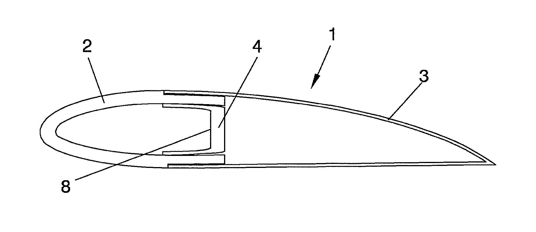
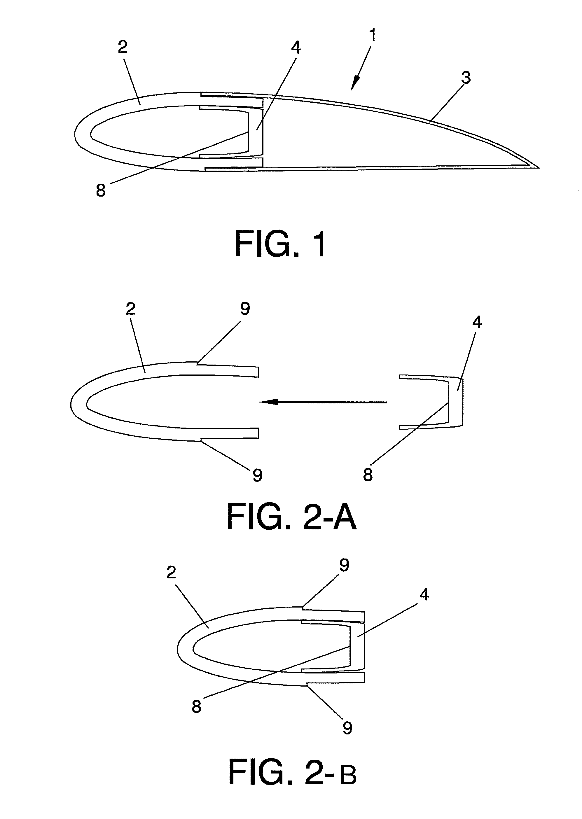
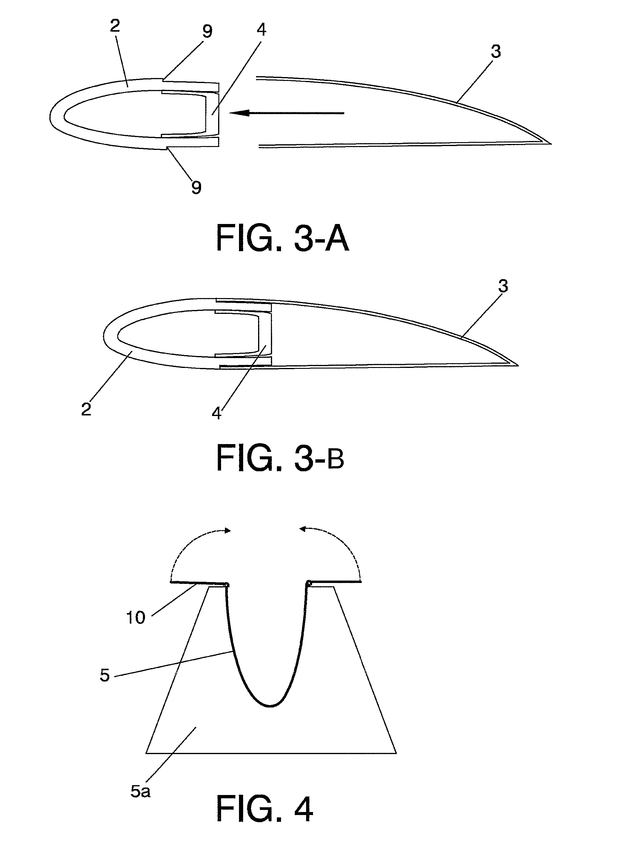
[0035]Considering said figures, we may observe that the procedure advocated is intended for the manufacture of a blade-like structure (1), which will be composed of a leading edge (2), a trailing edge (3) and, at least, one inner reinforcing side member (4) made up of pieces executed from sheets of prepreg material.

[0036]To this end, said procedure comprises the use of a female mould of the leading edge (5) and a female mould of the trailing edge (6), as well as a third mould (7) whereby a male jig (8) is obtained that acts as a lost mould for manufacturing the structural side member (4) and which may be C- or closed-box or even double-T shaped, said male jig (8) being made from composite.

[0037]The inner sides of the afore-mentioned femal...


PUM

PropertyMeasurementUnit
Temperatureaaaaaaaaaa
Fractionaaaaaaaaaa
Timeaaaaaaaaaa

Abstract

The invention relates to a method for manufacturing wind turbine blades, blades for propellers, wings or similar structures, and to a structure in the shape of a blade produced by means of said method, including: use a female mold of the leading edge (5), a female mold of the trailing edge (6), and a third mold (7) for a composite male tool (8) as a lost mold for manufacturing at least an inner crossbeam (4); wherein a demolding agent and an outer protective varnish is applied on the inner sides by robot or a digitally-controlled device; applying prepreg in superimposed layers; coating the prepreg with a vaccum film, and connecting to a pump for extracting air from between the prepreg layers; fitting together the molds and positioning the pieces with the prepreg laminates; and applying pressure and thermal curve for the method of curing or polymerizing the set of pieces in a single stage or all at once.

Description

FIELD OF THE INVENTION[0001]As stated in the rationale of this descriptive report, the invention refers to a procedure for the manufacture of wind turbine blades, propeller blades, wings or similar structures and structure in the form of a blade or the like obtained by means of this procedure.[0002]More specifically, the object of the invention is focused, on the one hand, on a procedure that is specially designed for the manufacture of wind turbine blades or the like in a single stage or step, which we would call a “single biological process”, consisting of the upper surface of the blade, known as the “extrados”, the lower surface of the blade, known as the “intrados”, and the structural element or internal side member of the blade being formed at the same time.[0003]Furthermore, the process proposed envisages the use, as a product for the execution of the blades, of the type of material that is called “PREPREG”, consisting of a product composed of reinforcement fibres pre-impregna...

Claims


Application Information

Patent Timeline
IPC IPC(8): B21K3/04
CPCB21K3/04B29C70/44B29L2031/08F03D1/0675Y10T29/49337Y02E10/72Y02P70/50F03D1/0633F03D1/0641
Inventor GARCIA CASTRO, FRANCISCO JAVIERMANSO GARCIA, JUAN JOSE
Owner GARCIA CASTRO FRANCISCO JAVIER
Learn More