Compression-lift aircraft

a technology of compression lift and aircraft, which is applied in the direction of airflow influencers, transportation and packaging, wing shapes, etc., can solve the problems of increasing lift, and achieve the effects of reducing shock wave, increasing lift, and reducing drag

Active Publication Date: 2013-12-26
KOSHELEFF PATRICK ANDREW
View PDF0 Cites 19 Cited by
  • Summary
  • Abstract
  • Description
  • Claims
  • Application Information

AI Technical Summary

Benefits of technology

[0014]The keel is just wide enough to house the landing gear's wheel bogies one behind the other. One strut carrying a wheel bogie retracts upward and forward, the other strut retracts upward and backward. This tandem bogie storage makes for a slender keel, compared to the usual bulky hold volume under the passenger cabin.
[0015]The keel obtains drag reduction by virtue of being narrow. Narrowness has another use: The slender keel in combination with a wide-body fuselage. Then there is more fuselage bottom area for the shock pressure to push upward on, increasing lift.
[0016]Tip fins near the wingtips intercept the outboard half of the shock generated by a wedge. This achieves the reflected shock effect at the outer part of a wing. The tip fins have noses shaped like triangles with an acute angle. This high sweepback reduces the shock wave created by the fin itself. That causes less shock interference at the place on the fin where the wedge shock is reflected.

Problems solved by technology

The keel will cause such a shock to reflect off a side wall of the keel, increasing the lift.

Method used


Image

  • Compression-lift aircraft
  • Compression-lift aircraft
  • Compression-lift aircraft

Examples


Embodiment Construction

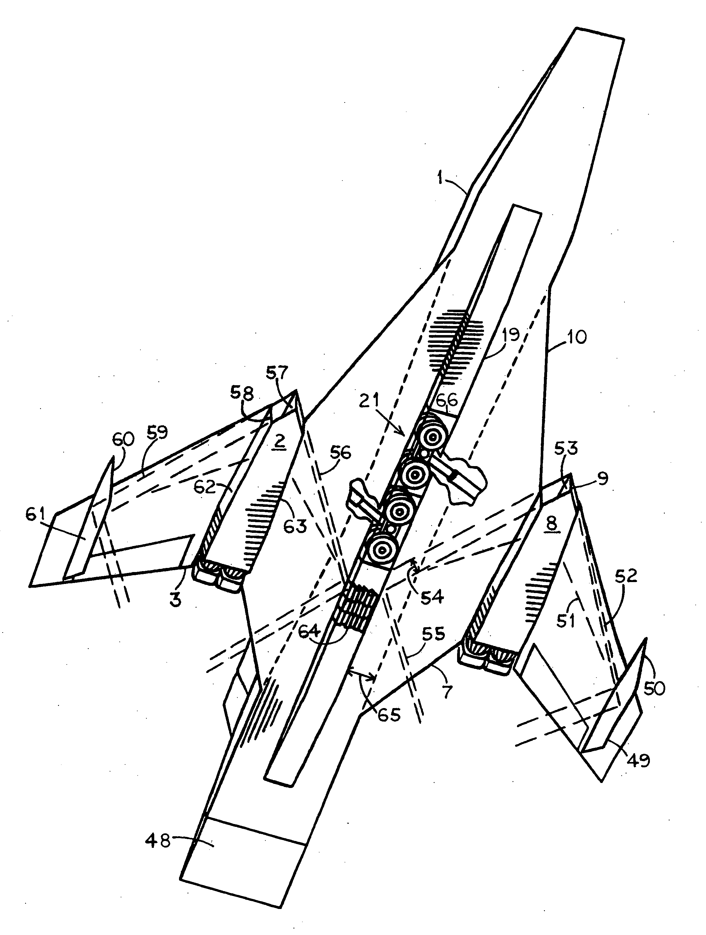
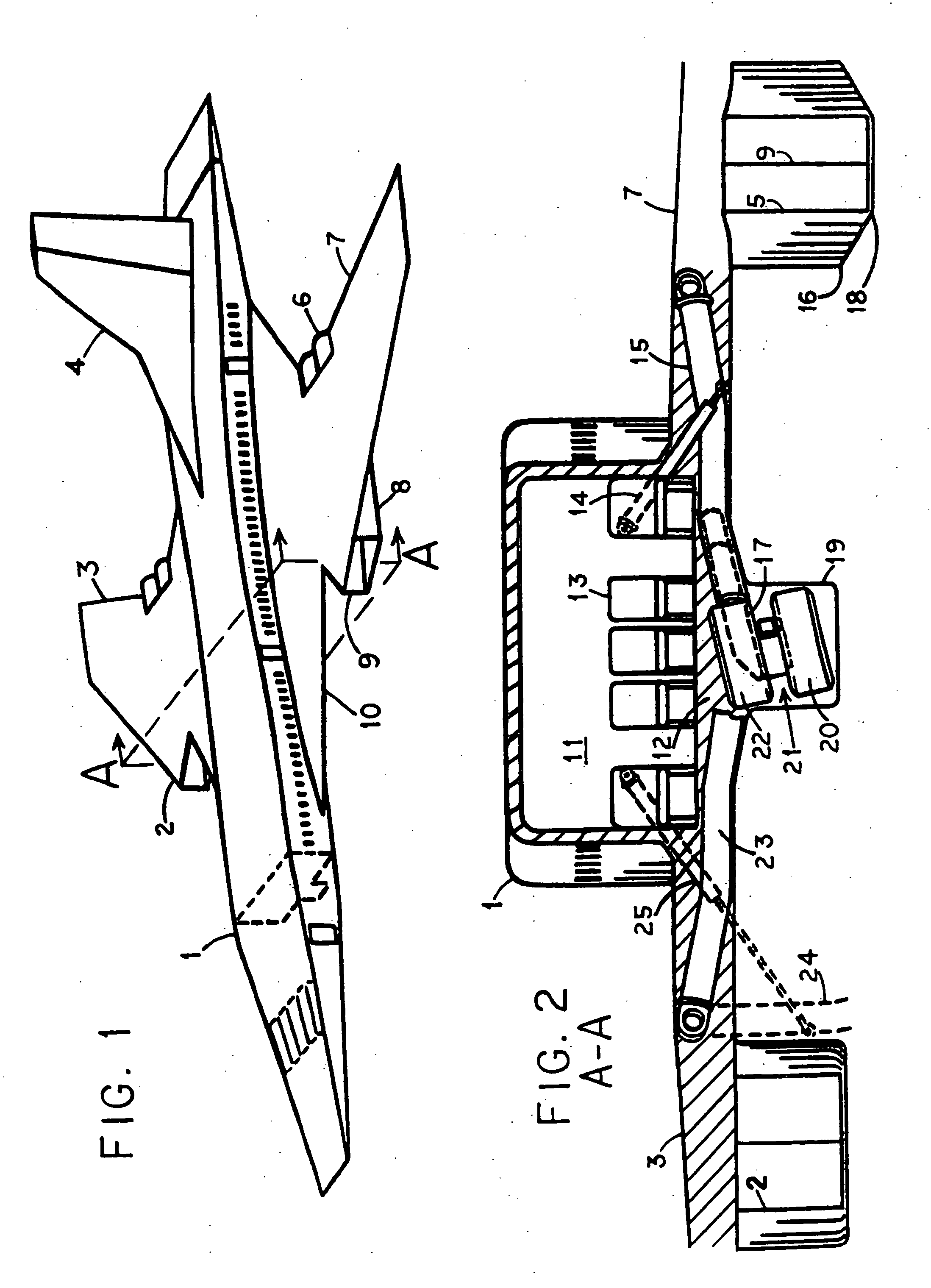
[0026]FIG. 1 shows an airliner design intended to cruise efficiently at Mach 2. There is a fuselage 1, wings 3 and 7, and a vertical tail 4 for directional stability. It takes a lot of power to fly at Mach 2 so there are four large turbojet engines such as 6 housed two to an engine nacelle 8. Knife-edge 9 at the front of a nacelle 8 splits the intake air into halves, one of them going to feed engine 6. A similar nacelle 2 is found under other wing 3.

[0027]There has already been a Mach 2 airliner, the Concorde which was in airline service for two decades. The layout of our aircraft design is similar except that Concorde's long-chord delta wings have been replaced by swept-back ones 3 and 7. At the right, the end of fuselage 1 is configured as an elevator, whose leverage is maximum for its control. Fuselage 1 narrows at cutting plane A-A, an application of area-ruling which offsets some of the wave drag caused by the bulge of wing root 10. Area-ruling is a known technique which won't ...


PUM


Abstract

A supersonic aircraft design using compression lift for enhanced cruise performance. Each engine nacelle at mid-span has a vertical wedge at the nose which creates shock waves under the wings. The increased pressure behind the shock waves pushes up on the wings, creating compression lift. The second part of the process is trapping the shocks by some vertical surfaces. The inboard shocks are intercepted by a keel under the fuselage. This causes the reflected shock effect, which increases compression lift. The keel is just wide enough to store the main landing gear's wheel bogies one behind the other. One strut carrying a wheel bogie retracts upward and forward. The other strut retracts upward and backward. This allows tandem bogie storage in the narrow keel, which reduces drag. Outboard shocks are trapped by wingtip fins with pointed noses to reduce shock interference at the point of shock trapping.

Description

BACKGROUND OF THE INVENTION[0001]A supersonic aircraft design for cruising efficiently at Mach 2. Engine nacelles are placed under each wing near mid-span. A wedge nose at each nacelle creates oblique shock waves to the sides. The shocks spread horizontally under the wings. The greater pressure behind the shocks pushes up on the wings, creating the phenomenon known as compression lift.[0002]Examples are found in U.S. Pat. No. 3,137,460 by the manufacturer of the XB-70 Mach 3 bomber. Most of the instances are for the XB-70's single, six engine nacelle under the fuselage. Although his FIG. 12 does show an individual engine nacelle under a wing, his conical nose spike 21 wastes half of the shock which spreads downward, away from the wing.[0003]A similar observation can be made for the B-58 Mach 2 bomber(JANE's All the World's Aircraft, 1960-61, page 288.) It has individual nacelles hanging from a delta wing. The round nacelle noses create conical oblique shocks. A small part of a shock...

Claims


Application Information

Patent Timeline
Patent Type & Authority Applications(United States)
IPC IPC(8): B64C30/00B64C3/58B64C1/00
CPCB64C30/00B64C1/0009B64C3/58B64C3/10B64C25/12B64D33/02B64D2033/026Y02T50/10
Inventor KOSHELEFF, PATRICK ANDREW
Owner KOSHELEFF PATRICK ANDREW
Why Eureka
Try Eureka