Turbine component casting core with high resolution region

a technology of high resolution and casting core, which is applied in the field of casting cores for turbine engine components, can solve the problems of increasing the difficulty of manufacturing components, imposing limitations on core design, and difficult to separate dies, and achieves high resolution features

Active Publication Date: 2013-12-26
MIKRO SYSYTEMS INC +1
View PDF2 Cites 24 Cited by
  • Summary
  • Abstract
  • Description
  • Claims
  • Application Information

AI Technical Summary

Benefits of technology

[0026]Other embodiments of interlocking engagement between the first and second core pieces may be used to irreversibly interlock first and second core pieces together by thermal deformation to create a three dimensional interlocking joint. In at least one embodiment, the first and second core pieces may be used to form at least a portion of a turbine airfoil for a gas turbine engine, such as, but not, limited to a turbine blade. The first core piece may be formed from a normal resolution region of the core using a first process of molding. The second core piece may be formed from a high resolution region of the core using lithographic molding, which is a method of molding different than the first process and effective to produce high resolution features. The high resolution region may have one or more high resolution features selected from the group consisting of a recess, cavity, opening, protrusion, channel, groove, slot, and depression. The first core piece may include a cavity, and the second core piece may include a protrusion. The first and second core pieces may be joined such that a first portion of the protrusion is received in at least a portion of the cavity. The protrusion may be heated via an intermediate thermal heat treatment process causing the protrusion to thermally deform to create a three dimensional interlocking joint between the first and second core pieces by allowing thermal creep to irreversibly interlock the first and second core pieces together such that the joint becomes physically locked together providing joint stability through thermal processing.

Problems solved by technology

The inclusion of such features can dramatically increase the difficulty of manufacturing the component.
The directions in which the segments of the dies are pulled apart to remove the core are important factors in the design of the core and impose limitations on the core design, as it must be ensured that the various die segments can be withdrawn without interference.
As the required number of separation planes increases, it becomes increasingly challenging to separate the dies and, at some point, it becomes impossible.
Thus, the design of the core can ultimately affect the design of the blade.
With the drive toward advanced cooling schemes, including near wall cooling, conventional core production methods alone will not be able to meet the requirements of the advanced designs.

Method used


Image

  • Turbine component casting core with high resolution region
  • Turbine component casting core with high resolution region
  • Turbine component casting core with high resolution region

Examples


Embodiment Construction

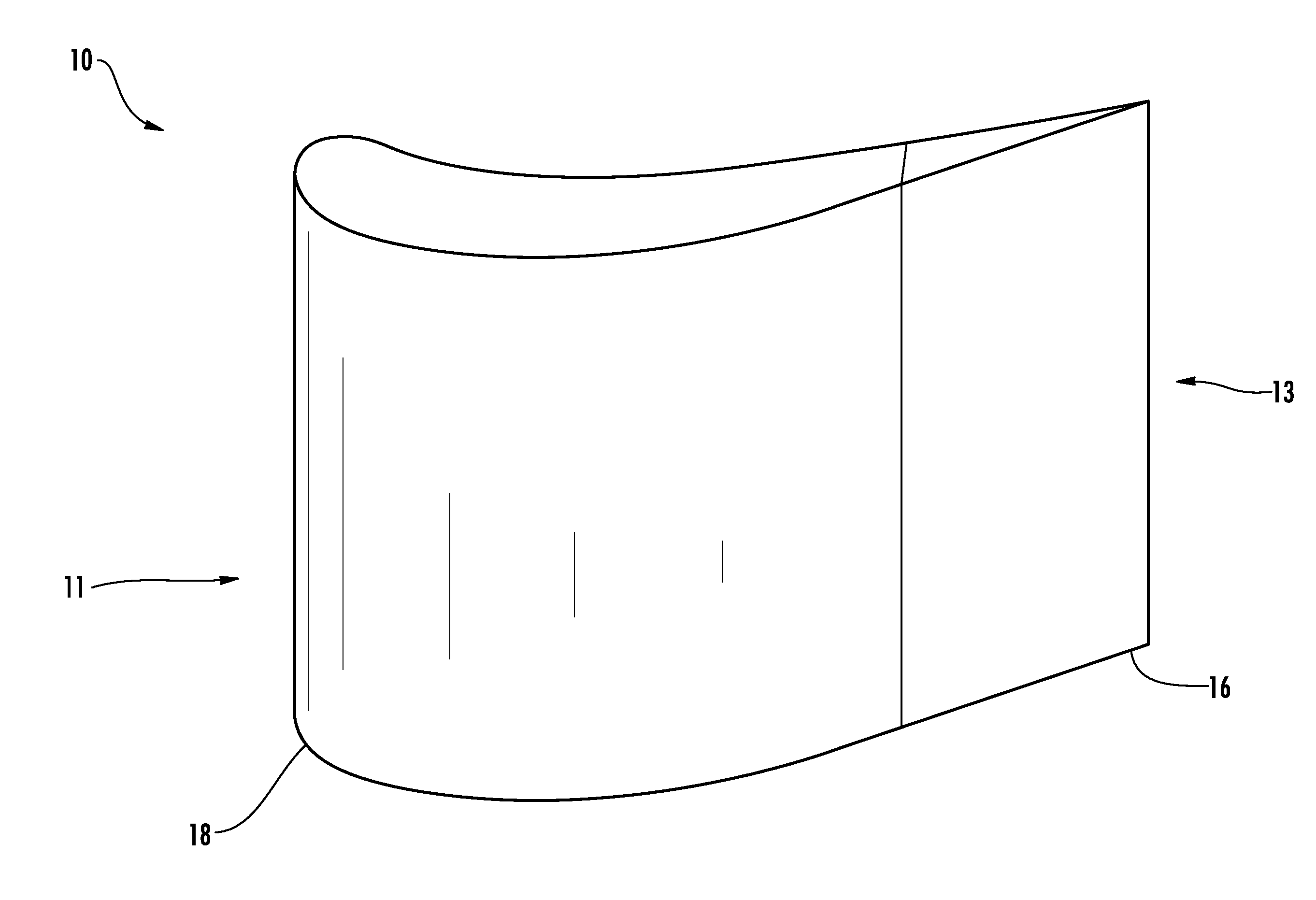
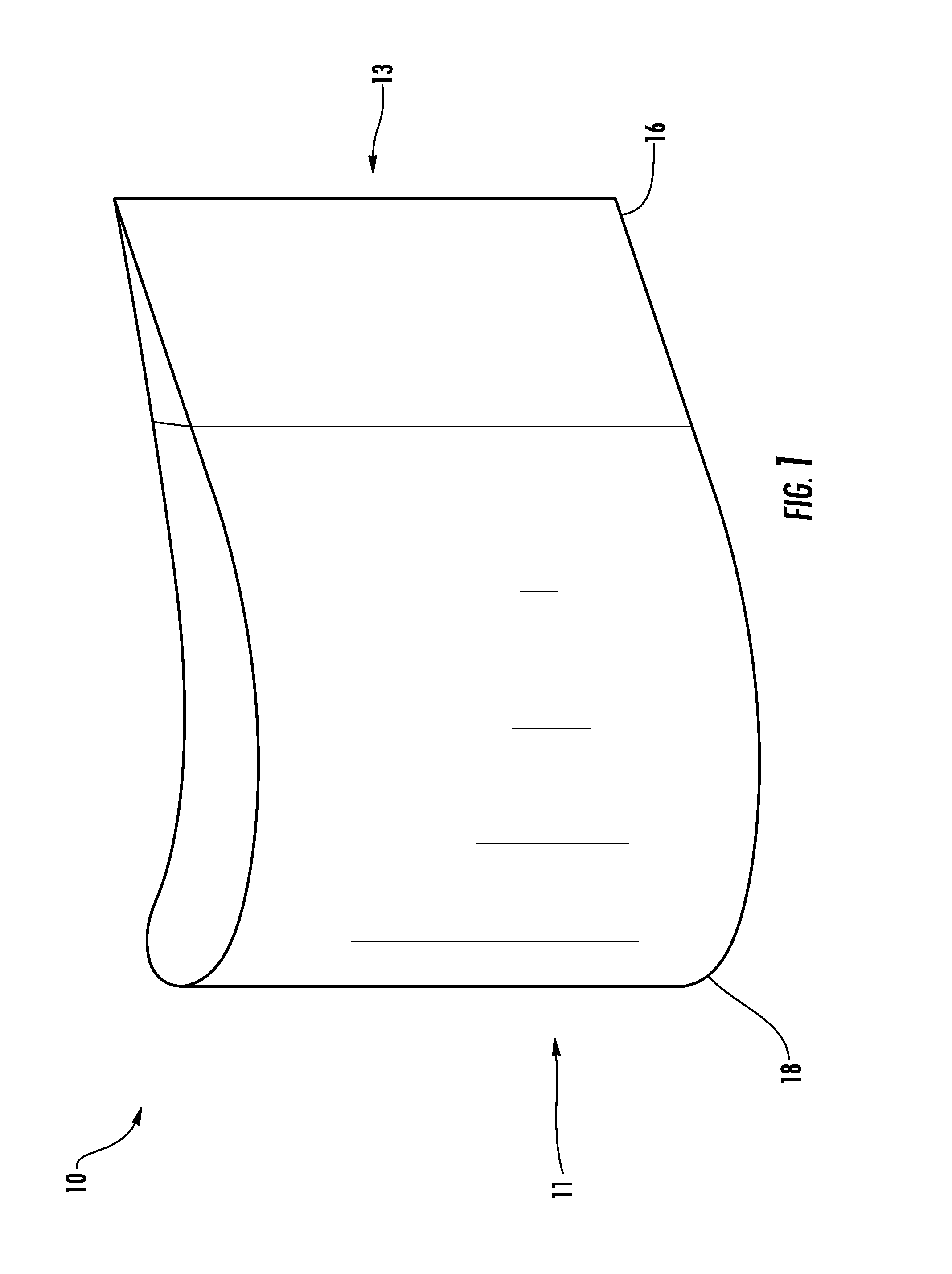
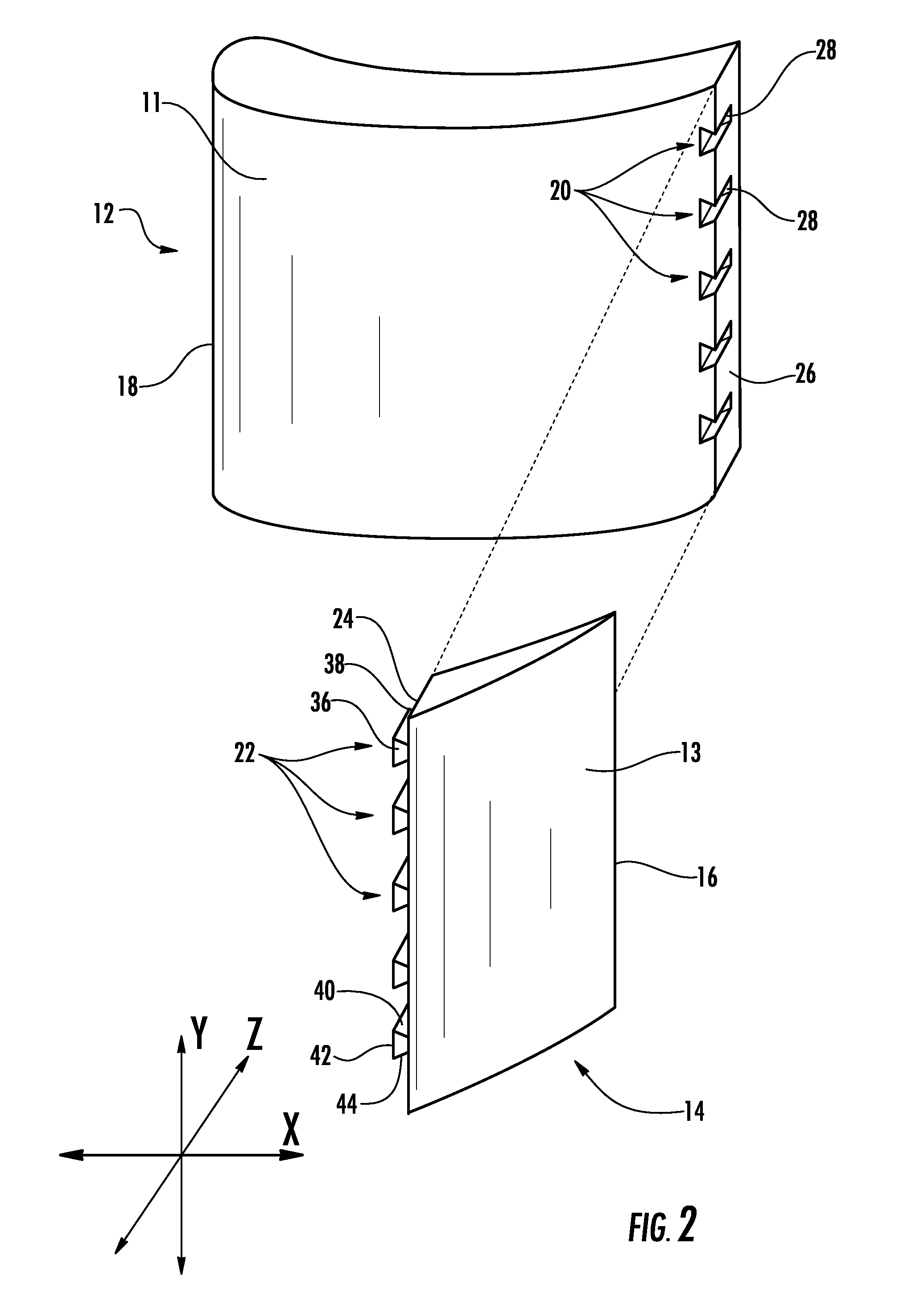
[0049]As shown in FIGS. 1-18, embodiments of the invention are directed to a casting core system with one or more high resolution regions for use in casting a turbine engine component. Aspects of the invention will be described in connection with a casting core for a turbine airfoil, but the detailed description is intended only as exemplary. Indeed, aspects of the invention can be used in connection with any hollow cast turbine engine component, especially those with complex internal features. Embodiments of the invention are shown in FIGS. 1-8, but the present invention is not limited to the illustrated structure or application.

[0050]Referring to FIG. 1, a casting core 10 according to aspects of the invention is shown. The casting core 10 can include a first region 11 and a second region 13. In one embodiment, the core 10 can be used in connection with the casting of a turbine blade or vane. In such case, the second region 13 can define an airfoil trailing edge portion 16 of the c...


PUM

PropertyMeasurementUnit
acute anglesaaaaaaaaaa
anglesaaaaaaaaaa
grain sizesaaaaaaaaaa

Abstract

A hollow turbine engine component with complex internal features can include a first region and a second, high resolution region. The first region can be defined by a first ceramic core piece formed by any conventional process, such as by injection molding or transfer molding. The second region can be defined by a second ceramic core piece formed separately by a method effective to produce high resolution features, such as tomolithographic molding. The first core piece and the second core piece can be joined by interlocking engagement that once subjected to an intermediate thermal heat treatment process thermally deform to form a three dimensional interlocking joint between the first and second core pieces by allowing thermal creep to irreversibly interlock the first and second core pieces together such that the joint becomes physically locked together providing joint stability through thermal processing.

Description

CROSS-REFERENCE TO RELATED APPLICATION[0001]This application is a continuation-in-part patent application of U.S. Utility patent application Ser. No. 12 / 712,632, filed Feb. 25, 2010, the entirety of which is incorporated herein.STATEMENT REGARDING FEDERALLY SPONSORED DEVELOPMENT[0002]Development for this invention was supported in part by Contract No. DE-FC26-05NT42644 awarded by the United States Department of Energy. Accordingly, the United States Government may have certain rights in this invention.FIELD OF THE INVENTION[0003]Aspects of the invention relate in general to turbine engine components and, more particularly, to cast turbine engine components.BACKGROUND OF THE INVENTION[0004]In a turbine engine, many components, such as turbine blades or vanes, are exposed to hot gases during engine operation. In order to withstand the operational environment, these components are typically cooled during engine operation. To promote cooling, these components can include a number of int...

Claims


Application Information

Patent Timeline
Patent Type & Authority Applications(United States)
IPC IPC(8): B29D99/00
CPCB29D99/0028B22C9/103
Inventor ELLGASS, DANIELFRASER, IAIN ALASDAIRJOUINI, DHAFERKAMEL, AHMEDORSINGER, GABRIEL V.
Owner MIKRO SYSYTEMS INC
Why Eureka
Try Eureka