
Cartridge set for manufacturing syringe and method for manufacturing dual-chamber type combined container-syringe

a technology of combined container and syringe, which is applied in the direction of manufacturing tools, packaging goods types, lighting and heating apparatus, etc., can solve the problems of difficult adjustment of the filling amount of solvent or powder preparation, difficulty in filling solvent, steam sterilization, etc., and achieves easy and smooth removal, easy adjustment of the position of the cartridge, and the effect of easy and smooth removal

Active Publication Date: 2013-12-26
ARTE
View PDF10 Cites 22 Cited by
  • Summary
  • Abstract
  • Description
  • Claims
  • Application Information

AI Technical Summary

Benefits of technology

This patent is about a cartridge set and manufacturing method for a dual-chamber type combined container-syringe. The main technical effects of this patent are that the cartridge can be easily positioned and that sterilization can be performed on the cartridge. The holder can be easily removed from below the cartridge without interfering with the front assembly. The cartridge set allows for the efficient and smooth insertion of each of the front, middle, and end stoppers into the syringe, as well as the filling or sealing of the solvent, injection drug solution, or powder preparation.

Problems solved by technology

Here, in the case of the dual-chamber type combined container-syringe, the filling of the solvent, the steam sterilization of the solvent after the filling, the aseptic filling of the powder preparation, the adjustment of the filling amount of the solvent or the powder preparation, and the like, are more difficult than the single-chamber type combined container-syringe.
Moreover, in the case of the dual-chamber type combined container-syringe, manufacturing steps are complicated and very difficult, such as being required to lyophilize a preparation, and insert and seal the stoppers within the lyophilizer.
When such a difficult steps are performed on a cartridge, constant precision cannot be ensured in a state where the front assembly or the finger grip is fitted to the cartridge.
Particularly, if the steam sterilization or the lyophilizing step is performed in a state where the front assembly or the finger grip is fitted, the front assembly or the finger grip may expand or contract, and the precision of assembling, the strength of the syringe or the like may be reduced and deteriorated.
However, in a case where it is intended to support only the cartridge on the supporting plate, since the finger grip is not fitted to the cartridge, the cartridge cannot be supported on the supporting plate with a backlash therebetween.
Accordingly, there is a possibility in that fine adjustment, such as position adjustment when the various stoppers or the like are inserted into the cartridge is difficult, and various steps cannot be smoothly performed.

Method used


Image

  • Cartridge set for manufacturing syringe and method for manufacturing dual-chamber type combined container-syringe
  • Cartridge set for manufacturing syringe and method for manufacturing dual-chamber type combined container-syringe
  • Cartridge set for manufacturing syringe and method for manufacturing dual-chamber type combined container-syringe

Examples


first embodiment

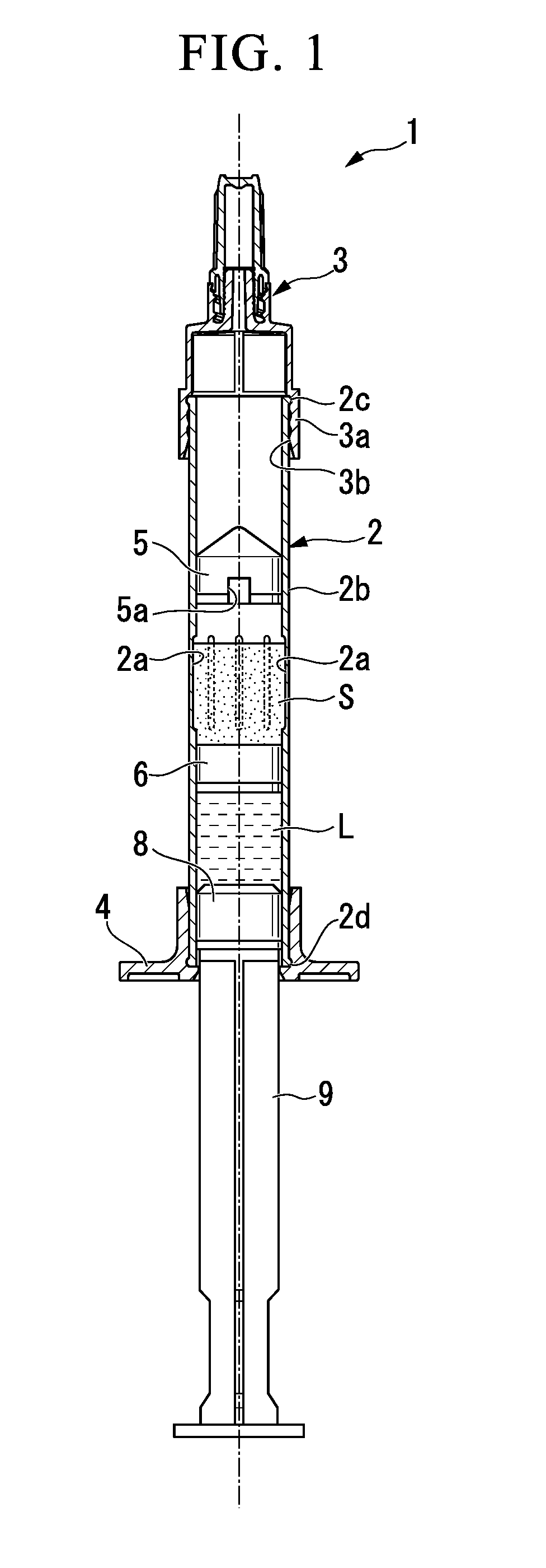
[0082]First, a dual-chamber type combined container-syringe (hereinafter simply referred to as “combined container-syringe”) manufactured by a method for manufacturing a dual-chamber type combined container-syringe will be described with reference to FIG. 1.

[0083]As shown in FIG. 1, a combined container-syringe 1 is equipped with a cartridge 2, a front assembly 3 that is attached to the tip end side (upper side in FIG. 1) of the cartridge 2, a finger grip 4 that is made of a synthetic resin and is fitted to the outer periphery of the cartridge 2 on the rear end side of the cartridge 2, stoppers of a front stopper 5, a middle stopper 6, and an end stopper 8 that are sequentially positioned in the cartridge 2 from the tip end side of the cartridge 2, and a rod-shaped plunger rod 9 that is connected to the end stopper 8 from the rear end side of the cartridge 2.

[0084]Lyophilized preparation (drug) S is filled between the front stopper 5 and the middle stopper 6, and a solvent L is fil...

second embodiment

[0141]That is, as shown in FIG. 13, in the bypass portion 102a of the combined container-syringe 101 of the second embodiment, a portion of the inner peripheral surface of the cartridge 102 is recessed radially outward, and the outer peripheral surface 2b bulges radially outward so as to correspond to this. Thereby, the outer peripheral surface 2b does not have a uniform outer diameter, and protrudes radially outward in a portion where the bypass portion 102a is formed.

[0142]Next, a cartridge set 110 for manufacturing a syringe used when manufacturing the above combined container-syringe 101 will be described with reference to FIGS. 14, 15A and 15B.

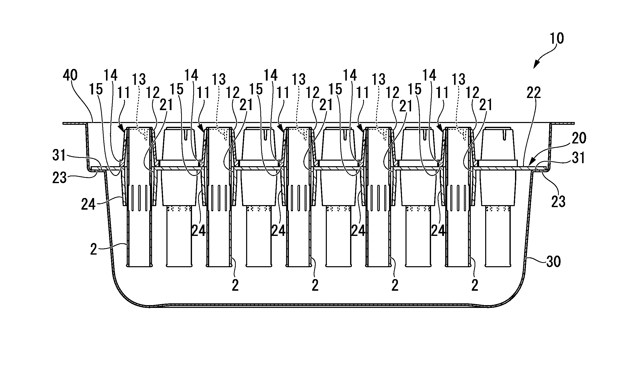
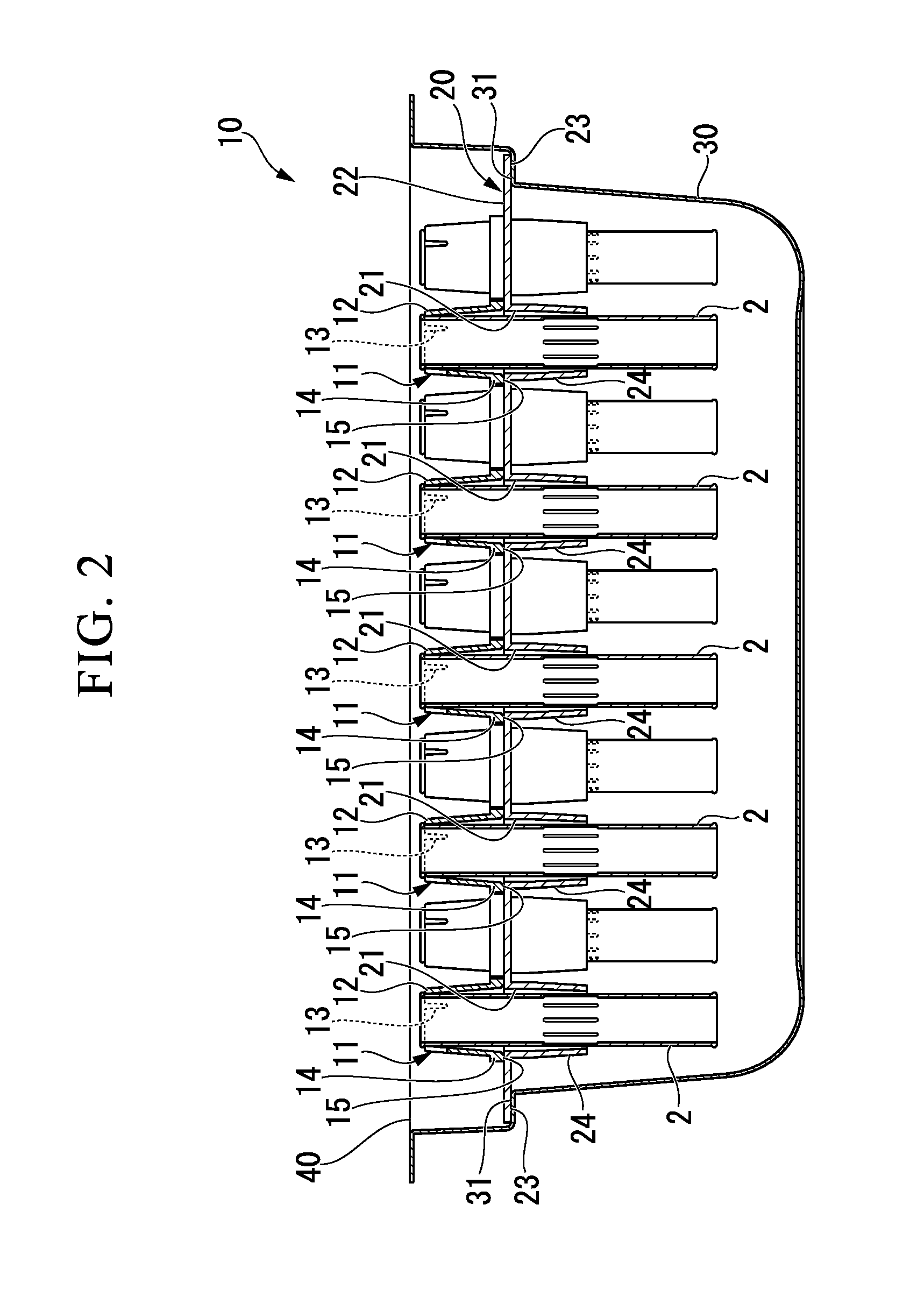
[0143]The cartridge set 110 for manufacturing a syringe is equipped with the above cartridges 102 arranged so as to extend in the up-and-down direction, the holders 11, a supporting plate 120, the storage box 30, and the lid member 40.

[0144]The supporting plate 120 of the present embodiment is different from the first embodiment only in t...


PUM

PropertyMeasurementUnit
Diameteraaaaaaaaaa

Abstract

A cartridge set including: a plurality of cartridges; a plurality of holders, each of which has an upper end externally fitted to the outer peripheral surface of each of the cartridges, and has a lower end face whose outer diameter is greater than the outer diameter of the outer peripheral surface of the cartridge; a supporting plate that has a plurality of through-holes, each of which has an inner diameter greater than the outer diameter of the outer peripheral surface of the cartridge and has each of the plurality of cartridges inserted therethrough; a storage box that stores the supporting plate therein; and a lid member that blocks an upper end opening of the storage box.

Description

BACKGROUND OF THE INVENTION[0001]1. Field of the Invention[0002]The present invention relates to a cartridge set for manufacturing a syringe which stores cartridges to be used when manufacturing a dual-chamber type combined container-syringe and a method for manufacturing a dual-chamber type combined container-syringe using the cartridge set for manufacturing a syringe.[0003]Priority is claimed on Japanese Patent Application No. 2012-138770, filed Jun. 20, 2012, the contents of which are incorporated herein by reference.[0004]2. Description of Related Art[0005]Combined container-syringes, which are designed so that an injection preparation is previously filled into the inside of a syringe and an injection can be given immediately to a patient by taking out the syringe from a packing at the time of use, have been widely adopted by medical institutions in all the countries of the world in terms of convenience, safety, and to prevent misuse of an injection drug.[0006]In recent years, s...

Claims


Application Information

Patent Timeline
IPC IPC(8): A61M5/00
CPCA61M5/002A61M5/008A61M5/19A61M5/2448A61M5/284B65B3/003B65B7/161B65B7/2821B65B31/00B65B63/08B65B2220/14B65B2220/24B65B2230/02F26B5/06Y10T29/49826
Inventor SHIMAZAKI, SEIJIKAKIUCHI, MAKOTOMATSUDA, TERUO
Owner ARTE
Learn More